0850/0850-T1 User Manual
Matrix Machine Tool (Coventry) Limited 159 / 231
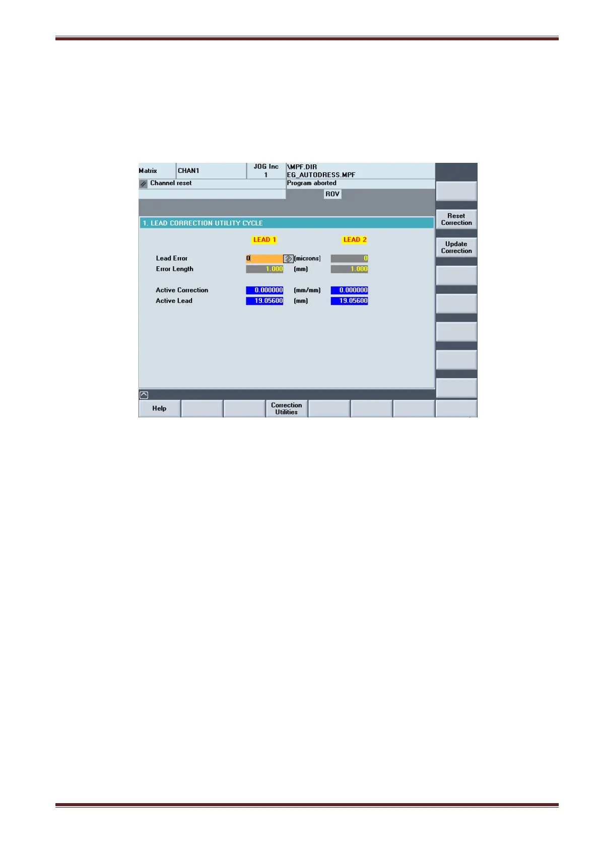
19.17 Lead Correction
Errors in the thread lead of the ground workpiece can be corrected for in the lead correction screen.
The lead error is corrected by entering the amount of error and the length over which the lead was
measured. The Lead Correction utility should be used when you need to correct for any errors to the
active lead introduced by the machine.
The screen shows two columns LEAD 1 and LEAD 2. The LEAD 2 column only applies to dual-lead
worm thread applications (option).
19.17.1 Explanation of input parameters
Lead Error
Input Range: 0 - 99 microns
Difference between the nominal length and the measured length
The lead error value can be positive or negative value.
Error Length
Input Range: 0 - 999 mm
Nominal length over which the lead error has been measured
The error length must always be a positive value. Also, the length along the workpiece where the
lead is checked does not matter.