0850/0850-T1 User Manual
Matrix Machine Tool (Coventry) Limited 149 / 231
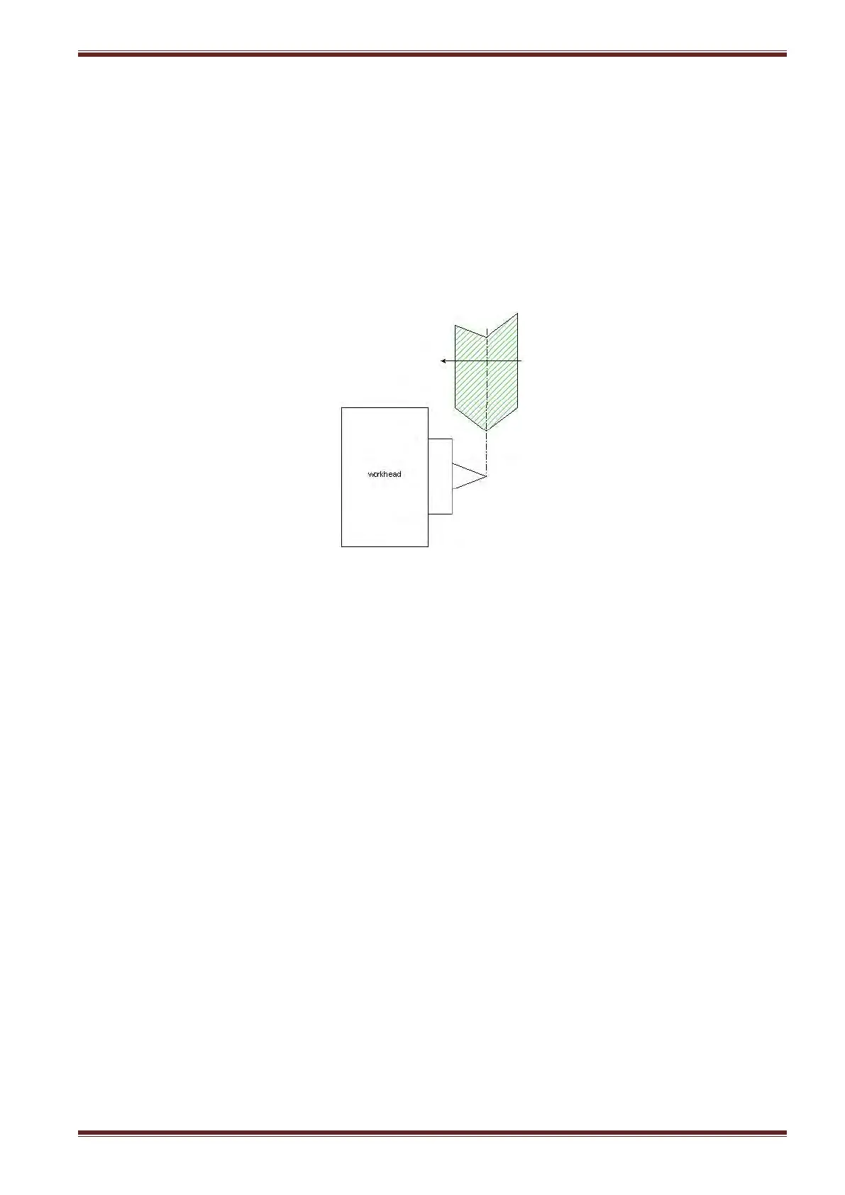
19.12.2 Procedure for setting up the probe system
The procedure below assumes that you have already fitted the probe system to the worktable and
connected it up to the service column.
1. Dress the grinding wheel with required profile
2. Set the wheel helix angle to 0° i.e A = 0.00
3. Select [JOG] mode and then using the handheld unit manually align the grinding wheel
position to the tip of the centre fitted to the workhead.
4. Make a note of the Z axis position as displayed on the screen in the machine coordinate
system (MCS).
5. Select the Probe Cycle screen [Custom > Matrix > Main Menu > Setting Cycles > Set Work
Datums > Probe Cycle] and enter the value you made a note of in the previous step into the
Fixture Offset input field.
6. Load a workpiece between centres.
7. Adjust the probing system position along the worktable until both the proximity sensor and
measuring stylus a somewhere close to the mid-point of the workpiece thread.
8. Clamp the probing system down to the table using a 17mm open-ended spanner.
9. Select the C axis and rotate the workpiece to the desired start position for the probing cycle.
Note: this step is optional.
10. Enter the C axis value as displayed on the screen in the MCS to the C Start Pos’n input field.
Note: If you are unsure about the workpiece start position from the previous step then just
set the value as 0.
11. Unload the workpiece.
12. Select [Probe Advance/Retract] at the machine control panel to bring the measuring stylus
into its probing position.