24.3 Preparatory Procedures for Monitoring
24.3.7 Checking for normal monitoring
24 - 27
17
CONNECTION TO
ALLEN-BRADLEY PLC
18
CONNECTION TO
SIEMENS PLC
19
MICROCOMPUTER
CONNECTION
20
CONNECTION TO OMRON
TEMPERATURE
CONTROLLER
21
CONNECTION TO
YAMATAKE TEMPERATURE
CONTROLLER
22
CONNECTION TO RKC
TEMPERATURE
CONTROLLER
23
CONNECTION TO
FREQROL SERIES
INVERTER
24
SERVO AMPLIFIER
CONNECTION
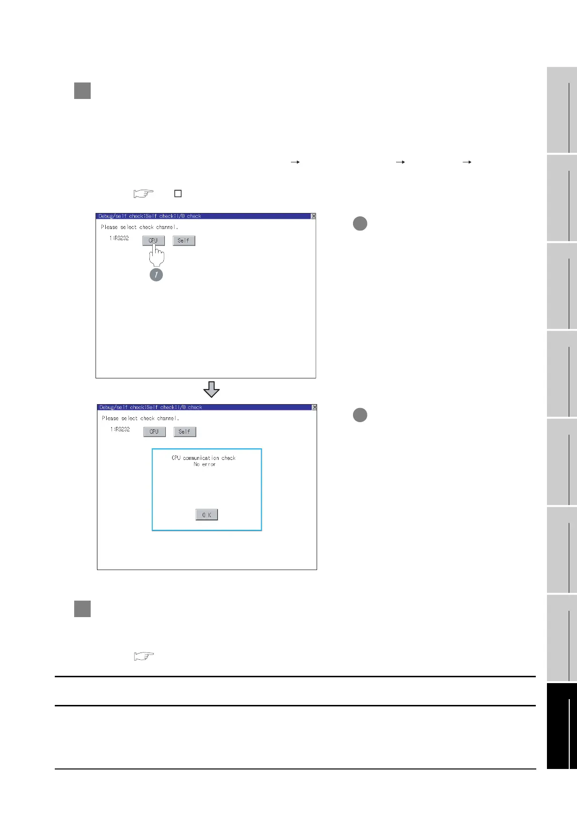
2 Perform an I/O check
Whether the servo amplifier can communicate with the GOT or not can be checked by the I/O check
function.
If this check ends successfully, it means correct communication interface settings and proper cable
connection.
Display the I/O check screen by [Main Menu] [Debug & self check] [Self check] [I/O check].
For details on the I/O check, refer to the following manual:
GT User's Manual
3 Confirming the servo amplifier side setting
When connecting the GOT, setting is required for the servo amplifier side.
Confirm if the servo amplifier side setting is correct.
Section 24.4 Setting on Servo Amplifier Side
1 Touch [CPU] on the I/O check screen.
Touching [CPU] executes the
communication check with the
connected servo amplifier.
2 When the communication screen
ends successfully, the screen on the
left is displayed.
All settings related to communications are complete now.
Create screens on GT Designer2 and download the project data again.

 Loading...


