19.3 Connection Cable
19.3.2 RS-422 cable
19 - 9
17
CONNECTION TO
ALLEN-BRADLEY PLC
18
CONNECTION TO
SIEMENS PLC
19
MICROCOMPUTER
CONNECTION
20
CONNECTION TO OMRON
TEMPERATURE
CONTROLLER
21
CONNECTION TO
YAMATAKE TEMPERATURE
CONTROLLER
22
CONNECTION TO RKC
TEMPERATURE
CONTROLLER
23
CONNECTION TO
FREQROL SERIES
INVERTER
24
SERVO AMPLIFIER
CONNECTION
19.3.2 RS-422 cable
The following shows the connection diagrams and connector specifications of the RS-422 cable used for
connecting the GOT to a microcomputer.
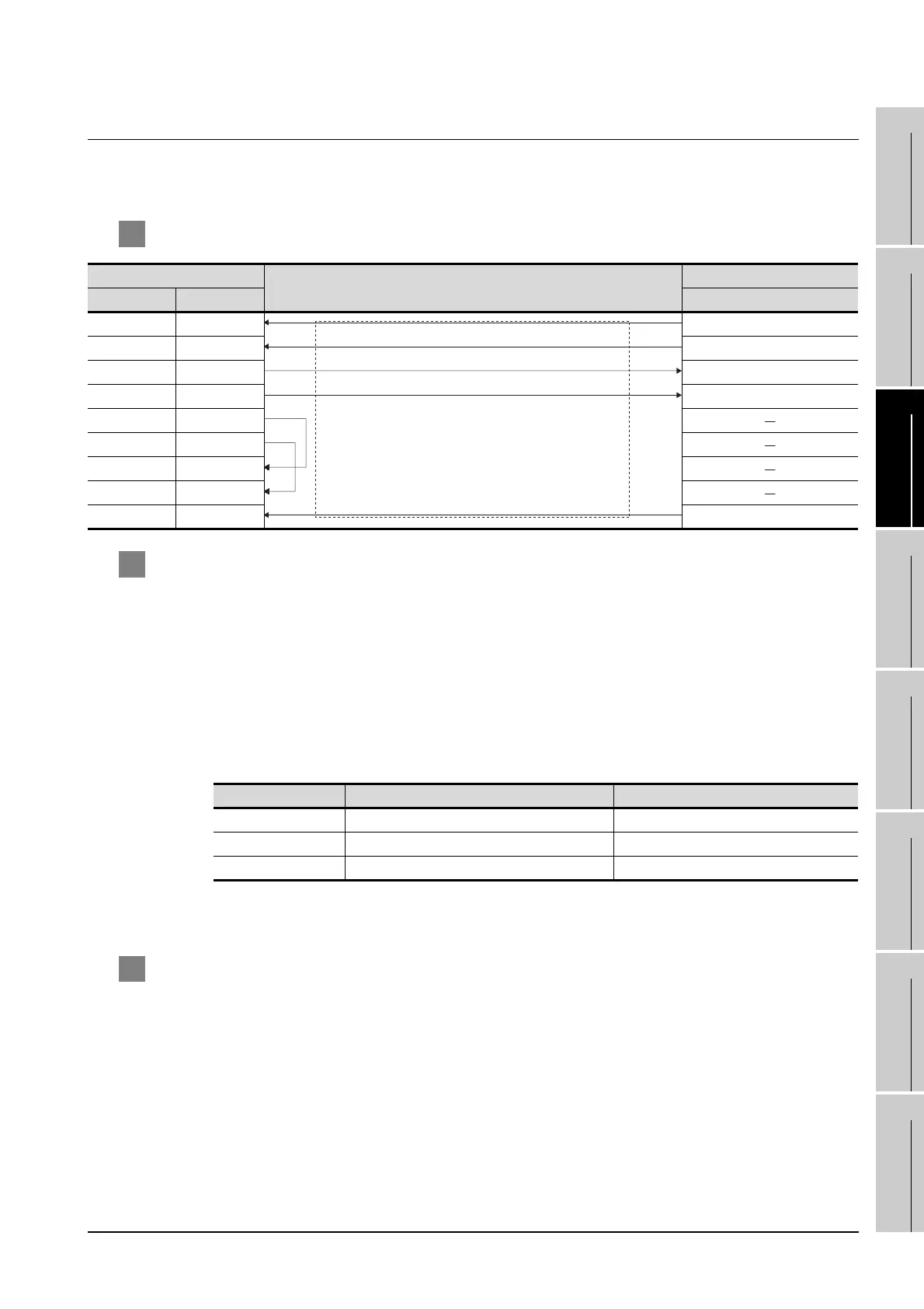
1 Connection diagram
2 Connector specifications
(1) GOT side connector
Use the following as the RS-422 interface and RS-422/485 communication unit connector on the
GOT.
For the GOT side of the RS-422 cable, use a connector and connector cover applicable to the GOT
connector.
(a) Connector type
9-pin D-sub (female)
(b) Connector model
(2) Host side connector
Use the connector compatible with the host side.
3 Precautions when preparing a cable
The length of the RS-422 cable must be 1200m or less.
GOT side
Cable connection and signal direction
Host side
Signal name Pin No. Signal name
RDA 2 SDA
RDB 7 SDB
SDA 1 RDA
SDB 6 RDB
RSA 3
RSB 8
CSA 4
CSB 9
SG 5 SHELL
GOT Model Manufacturer
RS-422 conversion unit 17LE-13090-27(D2AC) DDK Ltd.
GT11 17LE-13090-27(D3AC) DDK Ltd.
GT15-RS4-9S 17LE-13090-27(D3AC) DDK Ltd.
 Loading...


