19.3 Connection Cable
19.3.1 RS-232 cable
19 - 7
17
CONNECTION TO
ALLEN-BRADLEY PLC
18
CONNECTION TO
SIEMENS PLC
19
MICROCOMPUTER
CONNECTION
20
CONNECTION TO OMRON
TEMPERATURE
CONTROLLER
21
CONNECTION TO
YAMATAKE TEMPERATURE
CONTROLLER
22
CONNECTION TO RKC
TEMPERATURE
CONTROLLER
23
CONNECTION TO
FREQROL SERIES
INVERTER
24
SERVO AMPLIFIER
CONNECTION
19.3 Connection Cable
The RS-232 or RS-422 cable used for connecting the GOT to the microcomputer should be prepared by the
user.
The following provides connection diagrams for each cable, connector specifications and other information.
19.3.1 RS-232 cable
The following shows the connection diagrams and connector specifications of the RS-232 cable used for
connecting the GOT to a microcomputer.
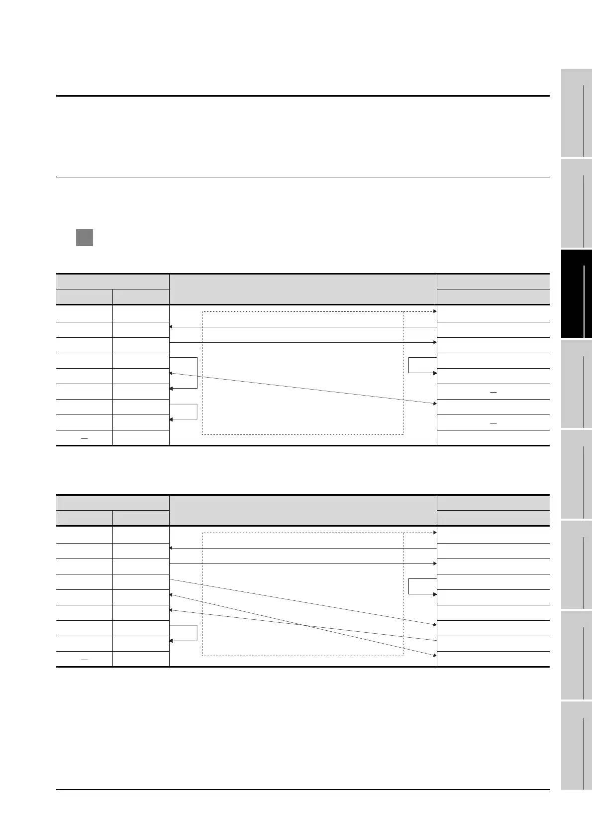
1 Connection diagram
(1) Example of the case where the DTR/DSR signal is not used
*1 GT15:CD, GT11:NC
(2) Example of the case where the DTR/DSR signal is used
*2 GT15:CD, GT11:NC
GOT side
Cable connection and signal direction
Host side
Signal name Pin No. Signal name
CD/NC
*1
1 FG
RD(RXD) 2 SD(TXD)
SD(TXD) 3 RD(RXD)
ER(DTR) 4 RS(RTS)
SG 5 CS(CTS)
DR(DSR) 6
RS(RTS) 7 SG
CS(CTS) 8
9 ER(DTR)
GOT side
Cable connection and signal direction
Host side
Signal name Pin No. Signal name
CD/NC
*2
1 FG
RD(RXD) 2 SD(TXD)
SD(TXD) 3 RD(RXD)
ER(DTR) 4 RS(RTS)
SG 5 CS(CTS)
DR(DSR) 6 5V
RS(RTS) 7 DR(DSR)
CS(CTS) 8 ER(DTR)
9 SG

 Loading...


