19.5 Message Formats
19.5.6 Formats 11 to 13 (Digital Electronics Corporation's memory link method)
19 - 53
17
CONNECTION TO
ALLEN-BRADLEY PLC
18
CONNECTION TO
SIEMENS PLC
19
MICROCOMPUTER
CONNECTION
20
CONNECTION TO OMRON
TEMPERATURE
CONTROLLER
21
CONNECTION TO
YAMATAKE TEMPERATURE
CONTROLLER
22
CONNECTION TO RKC
TEMPERATURE
CONTROLLER
23
CONNECTION TO
FREQROL SERIES
INVERTER
24
SERVO AMPLIFIER
CONNECTION
19.5.6 Formats 11 to 13 (Digital Electronics Corporation's memory link method)
1 Basic format of data communication
This is the same format as the protocol of the Digital Electronics Corporation's memory link method.
For details of the basic format of data communication, refer to the following manual:
The connection manual of the device manufactured by Digital Electronics Corporation
This section describes items whose settings differ from the protocols of the Digital Electronics
Corporation's memory link method and dedicated commands for a microcomputer connection of GOT.
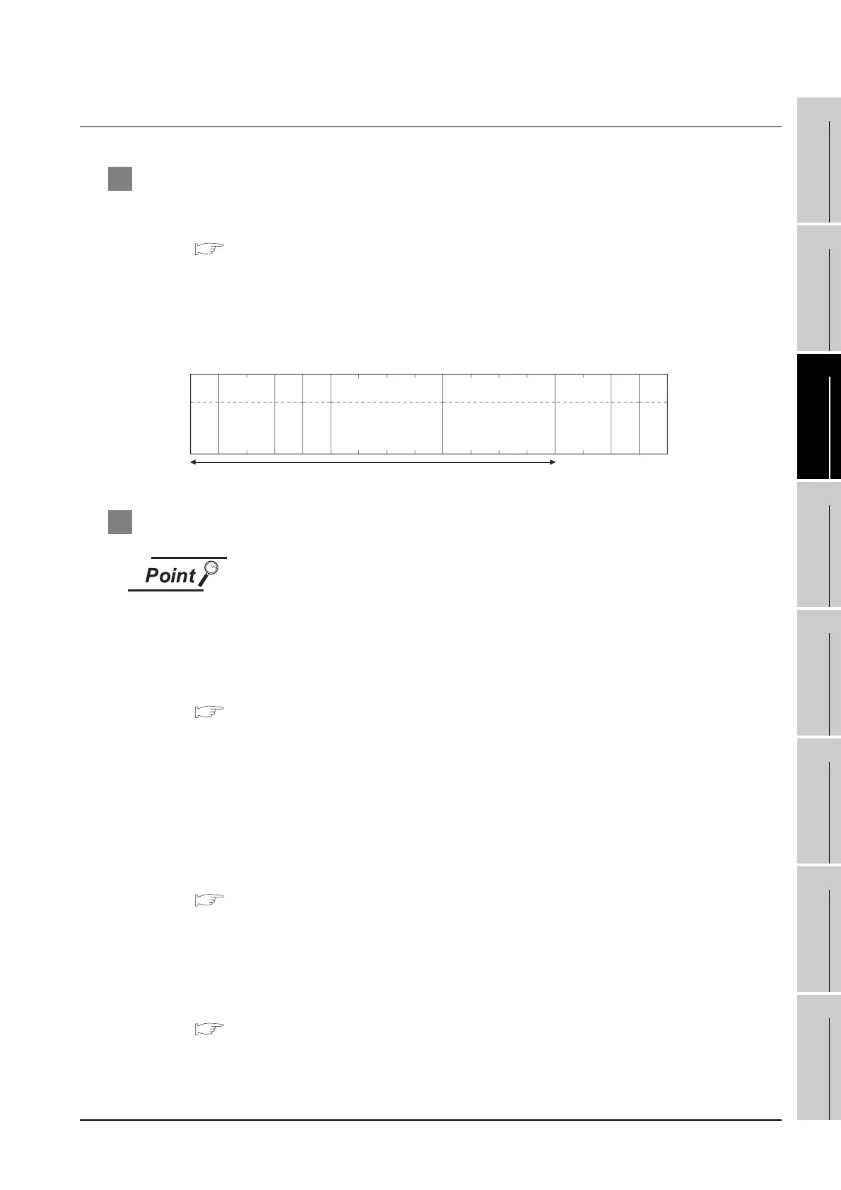
Example: Request message for the batch read in word units (R) command in format 13 (Digital
Electronics Corporation's memory link method (extended mode, ASCII code 1:n))
2 Details of data items in message format
Data code during communication
Communication is performed in ASCII code.
(1) Command
Specifies the items to access from the host to GOT.
The command is converted to a 1-digit ASCII code (Hex) and transmitted.
For details of the commands that can be used, refer to the following.
Section 19.5.2 List of commands
(2) Station No.
Station No. is used to identify the GOT with which the host communicates. (Setting range: 0 to 1F
H)
Data notated in Hex is converted to a 2-digit ASCII code (Hex) and transmitted from the upper digit.
The GOT processes only commands whose station No. matches the "Host Address (0 to 31)" set at
"Communication Detail Settings". (The messages of commands whose station No. do not match
are ignored.)
For details of setting "Communication Detail Settings", refer to the following.
Section 19.6.3 Setting communication interface (Communication settings)
(3) Address
Specifies the head No. of the device data to be read/written.
Data notated in Hex is converted to a 4-digit ASCII code (Hex) and transmitted from the upper digit.
For details of the device range that can be accessed, refer to the following.
Section 19.4 Device Data Area
Sum check is performed in this range.
05
H
ENQ
(H) (L)
5E
35H 45H
Sum
Check
(H) (L)
Station No.
0
30
H
0
30
H
(H) –
Address
0
30
H
4
34
H
– (L)
0
30
H
6
36
H
(H) –
Number of points
0
30
H
0
30
H
– (L)
0
30
H
2
32
H1BH
ESC
52H
R
0D
H
CR
0AH
LF
Com-
mand

 Loading...


