29.4 Preparatory Procedure for Accessing
29.4.4 Accessing the PLC by the GX Developer
29 - 15
25
BAR CODE READER
CONNECTION
26
PRINTER CONNECTION
27
CNC CONNECTION
28
MULTI-CHANNEL
FUNCTION
29
FA TRANSPARENT
FUNCTION
30
MULTIPLE-GT11
CONNECTION FUNCTION
31
GATEWAY FUNCTION INDEX
29.4.4 Accessing the PLC by the GX Developer
1 When connecting the GOT and PC with RS-232
The following shows an access example by GX Developer (when connected to the QCPU (Q mode))
when the GOT and PC are connected by RS-232.
1 Click [Online] [Read from PLC] in GX
Developer.
2 Set the [PLC Series] to [QCPU (Q
mode)].
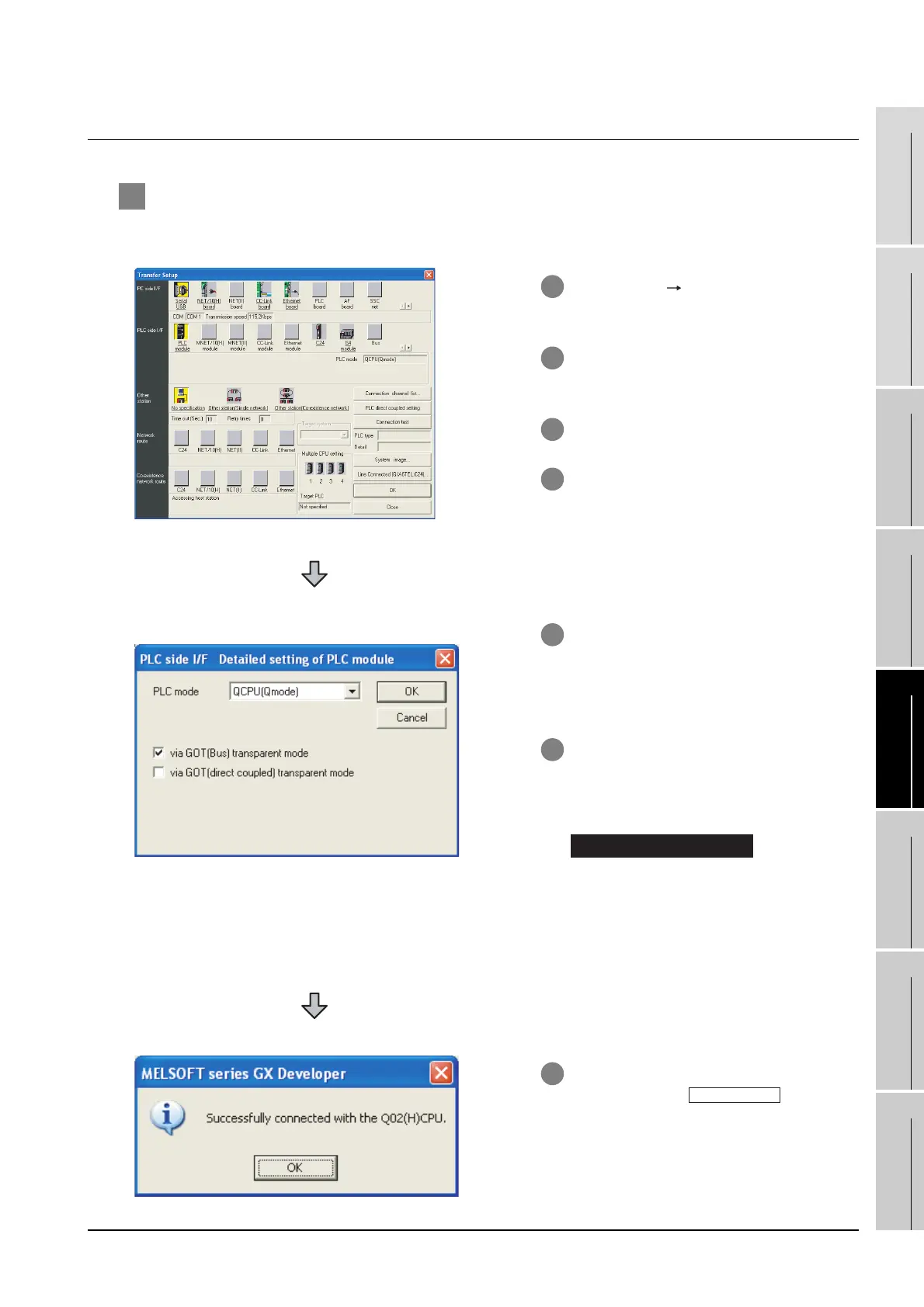
3 The [Connection Setup] is displayed.
4 Set the [Connection Setup]:
PC side I/F : Serial USB (COM)
PLC side I/F : PLC module
Other station : No specification
(For bus connection only)
5 When bus connection has been made,
double-click the [PLC module] on the
PLC side I/F to display the [PLC side I/F
Detailed setting of PLC module].
6 On the [PLC side I/F Detailed setting of
PLC module], mark the [via GOT(Direct
coupled) transparent mode] checkbox.
*1
For direct CPU connection,
mark the [via GOT (direct coupled)
transparent mode] checkbox.
*1 This is operation required in the case of
using GX Developer of which version is
8.22Y and above.
7 The screen returns to the [Connection
Setup]. Click the to check
if GX Developer has been connected to
the QCPU (Q mode).
Direct CPU connection
connection test

 Loading...


