11 - 18
11.2 Connection Cable
11.2.2 RS-422 cable
11.2.2 RS-422 cable
The following shows the connection diagrams and connector specifications of the RS-422 cable used for
connecting the GOT to a PLC.
1 Wiring diagram
(1) RS-422 cable 1)
*1 Connect the terminating resistor at pin 6 with pin 13 (RXD) only at the terminal station.
(Valid for JW-70CUH and JW-100CUH. The terminating resistor does not exist in JW-22CU and JW-100CU.)
(2) RS-422 cable 2)
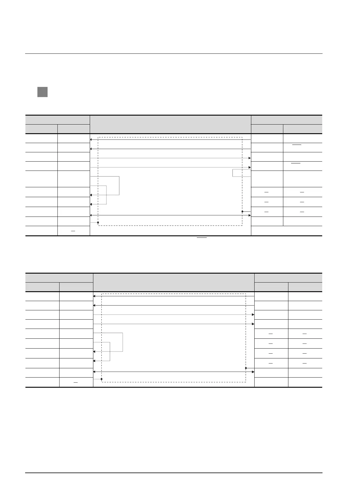
GOT side
Cable connection and signal direction
SHARP product side
Signal name Pin No. Pin No. Signal name
RDA 2 10 TXD(SD(+)
RDB 7 11 TXD(SD(-)
SDA 1 12 RXD(RD(+)
SDB 6 13 RXD(RD(-))
RSA 3 6
terminating
resistor*1
RSB 8
CSA 4
CSB 9
SG 5 7SG
FG
GOT side
Cable connection and signal direction
SHARP product side
Signal name Pin No. Pin No. Signal name
RDA 2 3SD(+)
RDB 7 11 SD(-)
SDA 1 9 RD(+)
SDB 6 10 RD(-)
RSA 3
RSB 8
CSA 4
CSB 9
SG 5 6SG
FG 7SG
 Loading...


