21 - 18
21.2 Connection Cable
21.2.2 RS-485 cable
21.2.2 RS-485 cable
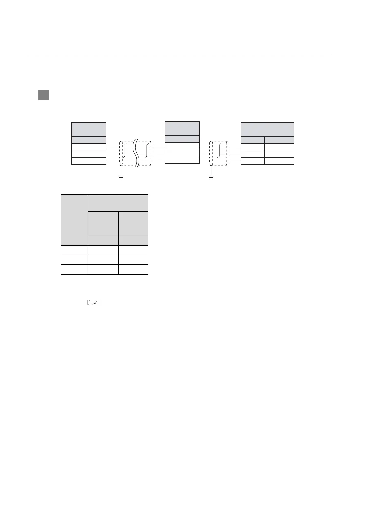
The following shows the connection diagrams and connector specifications of the RS-485 cable
used for connecting the GOT to a temperature controller.
1 Connection diagram
(1) RS-485 cable 1)
*1 Pin No. of temperature controller differs depending on model. Refer to the following table.
*2 Connect FG grounding to the single-sided end of a cable shield line.
*3 Set the terminal resister to “Disable”.
For details of terminating resistor settings, refer to the following.
Section 21.4.5 Connecting CMC10L
Signal
name
Model of temperature
controller
DMC10
SDC15
SDC25/26
SDC35/36
Pin No. Pin No.
DA 4 13
DB 5 14
SG 6 15
DA
SG
DB
*2 *2
Temperature
controller side
Signal name
*1
DA
SG
DB
Temperature
controller side
Signal name
*1
11
13
12
DA
SG
DB
(CMC10L)
Communication
controller side
*3
Pin No.
Signal name

 Loading...


