20.2 Connection Cable
20.2.1 RS-232 cable
20 - 9
17
CONNECTION TO
ALLEN-BRADLEY PLC
18
CONNECTION TO
SIEMENS PLC
19
MICROCOMPUTER
CONNECTION
20
CONNECTION TO OMRON
TEMPERATURE
CONTROLLER
21
CONNECTION TO
YAMATAKE TEMPERATURE
CONTROLLER
22
CONNECTION TO RKC
TEMPERATURE
CONTROLLER
23
CONNECTION TO
FREQROL SERIES
INVERTER
24
SERVO AMPLIFIER
CONNECTION
20.2.1 RS-232 cable
The following shows the connection diagrams and connector specifications of the RS-232 cable used for
connectiong the GOT to a temperature controller.
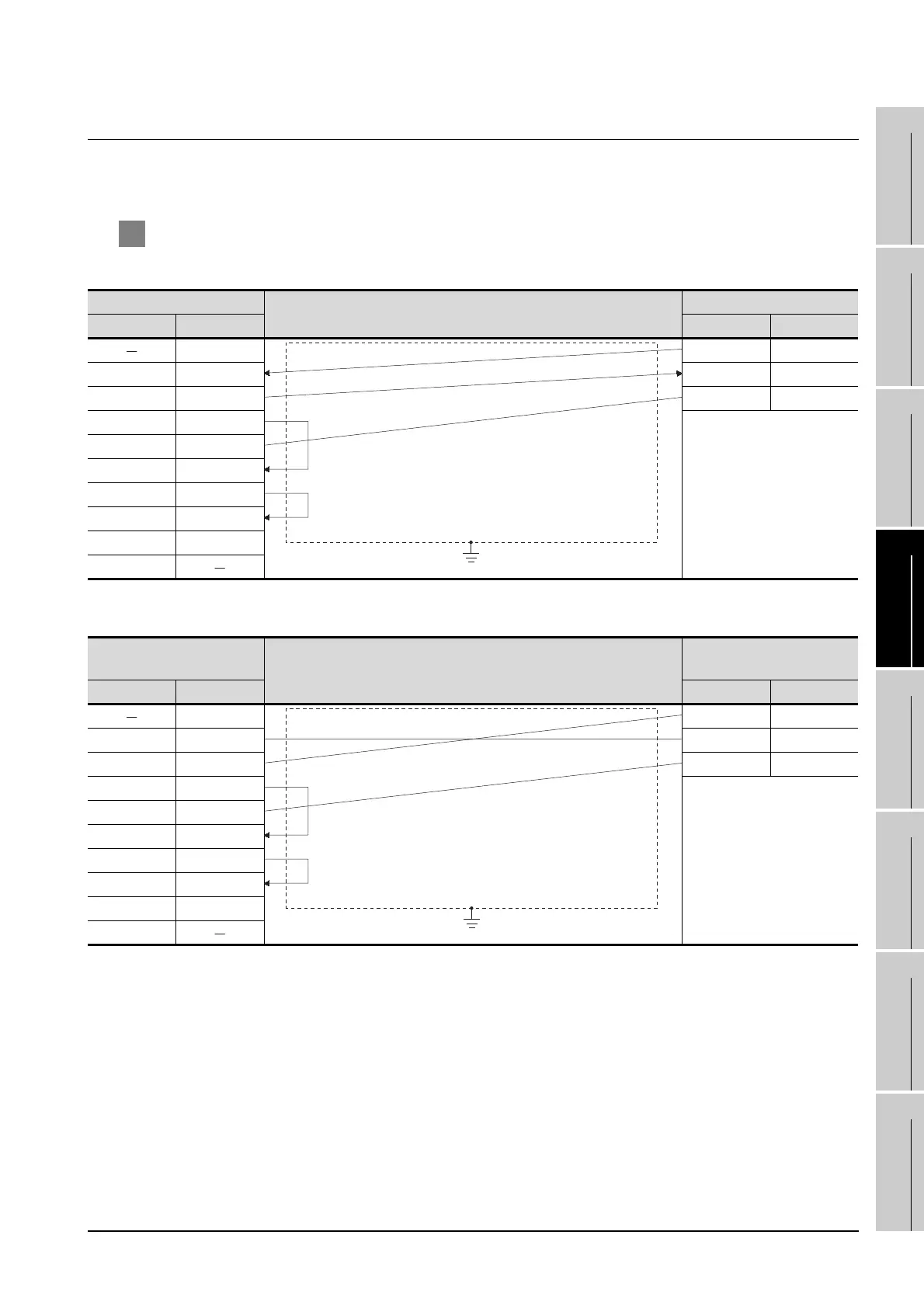
1 Connection diagram
(1) RS-232 cable 1)
(2) RS-232 cable 2)
GOT side
Cable connection and signal direction
OMRON product side
Signal name Pin No. Pin No. Signal name
1 11 SD
RD(RXD) 2 12 RD
SD(TXD) 3 13 SG
ER(DTR) 4
SG 5
DR(DSR) 6
RS(RTS) 7
CS(CTS) 8
NC 9
FG
GOT side
Cable connection and signal direction
OMRON product side
Interface converter (K3SC-10)
Signal name Pin No. Pin No. Signal name
1 5SD
RD(RXD) 2 6RD
SD(TXD) 3 3SG
ER(DTR) 4
SG 5
DR(DSR) 6
RS(RTS) 7
CS(CTS) 8
NC 9
FG

 Loading...


