EasyManuals Logo

Mitsubishi GOT1000 Series User Manual

Mitsubishi GOT1000 Series
1216 pages
To Next Page IconTo Next Page
To Previous Page IconTo Previous Page
Page #39 background imageLoading...
Page #39 background image
1.2 Overall System Configurations
1 - 7
1
OVERVIEW
2
BUS CONNECTION
3
DIRECT CONNECTION
TO CPU
4
COMPUTER LINK
CONNECTION
5
MELSECNET/10
CONNECTION (PLC TO
PLC NETWORK)
6
CC-Link CONNECTION
(INTELLIGENT DEVICE
STATION)
7
CC-Link CONNECTION
(Via G4)
8
ETHERNET
CONNECTION
1.2 Overall System Configurations
The following shows the system configurations for each GOT model.
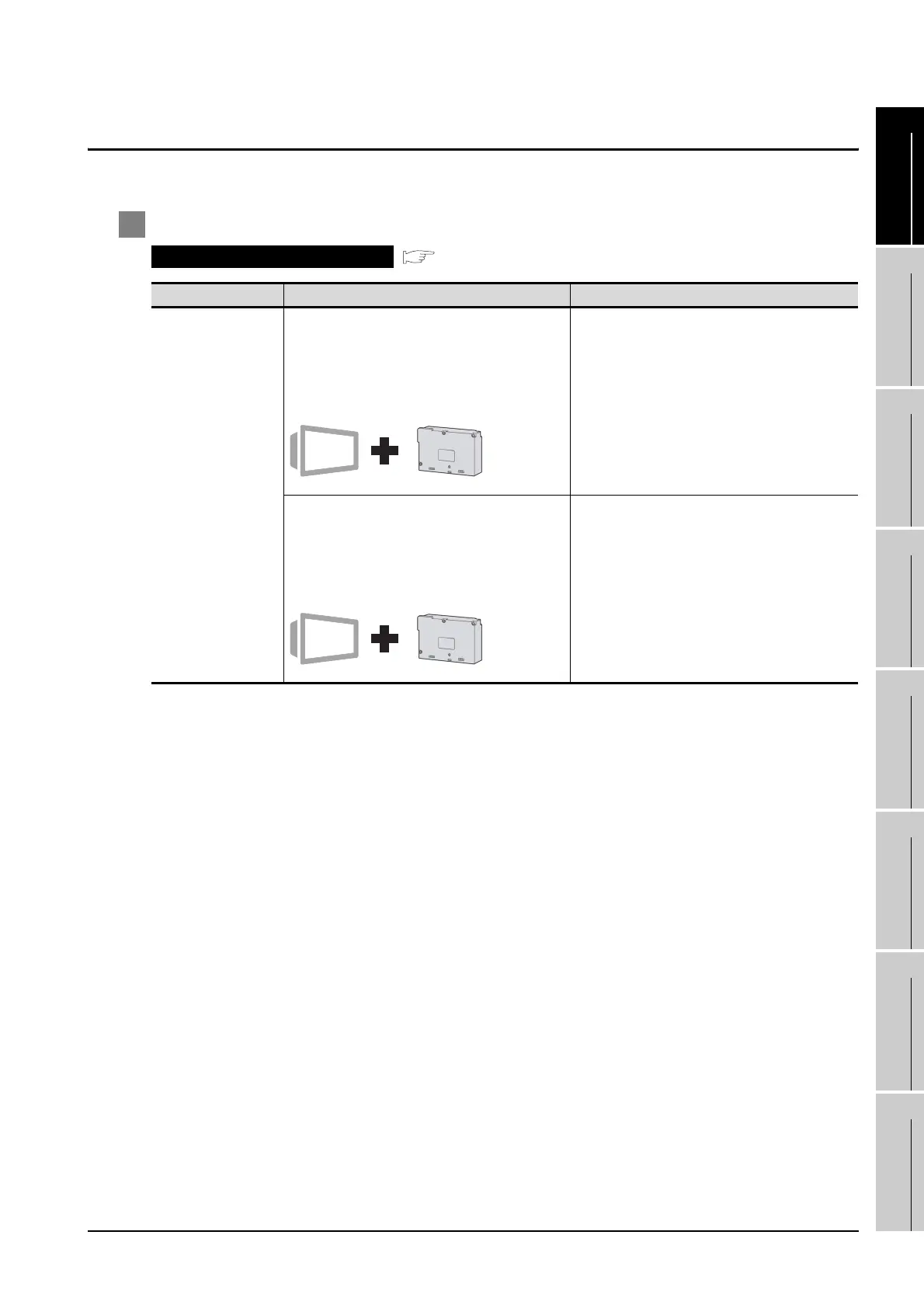
1 GT15 system configuration
Bus connection
( Chapter 2)
Communication Type Communication Interface on GOT Side Connected to
Bus connection
Bus connection unit
GT15-75QBUSL
GT15-75QBUS2L
•GT15-QBUS
•GT15-QBUS2
QCPU (Q mode)
Motion controller CPU (Q Series)
Bus connection unit
GT15-75ABUSL
GT15-75ABUS2L
GT15-ABUS
GT15-ABUS2
•QnACPU
•ACPU
Motion controller CPU (A Series)

Table of Contents

Questions and Answers:

Question and Answer IconNeed help?

Do you have a question about the Mitsubishi GOT1000 Series and is the answer not in the manual?

Mitsubishi GOT1000 Series Specifications

General IconGeneral
Power Supply24 VDC
TypeHMI (Human Machine Interface)
SeriesGOT1000
Resolution640 x 480 pixels
Touch Panel TypeResistive
InterfaceRS-232, USB
Storage Temperature-20 to 60°C
Protection RatingIP65
Display TypeTFT LCD
Brightness400 cd/m²
Backlight Life50, 000 hours
CPURISC
Shock Resistance147 m/s²
Display Size10.4 inches

Related product manuals