11 - 40
11.4 PLC Side Setting
11.4.4 Connecting to the link unit (JW-10CM or ZW-10CM)
11.4.4 Connecting to the link unit (JW-10CM or ZW-10CM)
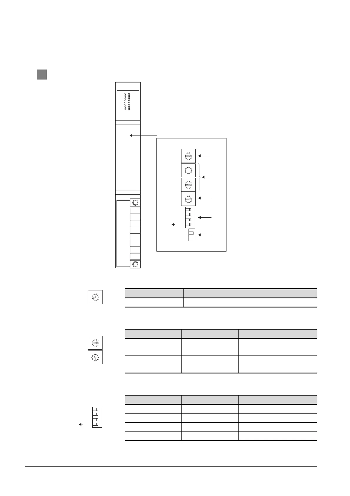
1 Switch setting of link unit (JW-10CM and ZW-10CM)
(1) Function setting switch(SW0)
(2) Station number switch(SW1,CSW2)
(3) Operation mode setting switch(SW3)
Setting Description
4 (fixed) Computer link(command mode)
Switch No. Setting Description
SW1
Station No. lower digit
(10
0
digit)
1 (fixed)
SW2
Station No. upper digit
(10
1
digit)
0 (fixed)
Switch No. Setting Description
SW3-1 OFF (fixed) Invalid
SW3-2 ON (fixed) 4-wire type
SW3-3 OFF (fixed) Invalid
SW3-4 ON (fixed) Even
3
2
0
5
9
4
8
7
6
1
3
2
0
5
9
4
8
7
6
1
3
2
0
5
9
4
8
7
6
1
3
2
0
5
9
4
8
7
6
1
4
SW1
SW2
SW0
SW4
SW3
SW7
3
2
1
ON
OFF
(1)
(2)
(4)
(3)
(5)
ON
Inside the cover of switch setting
3
2
0
5
9
4
8
7
6
1
SW0
3
2
0
5
9
4
8
7
6
1
3
2
0
5
9
4
8
7
6
1
SW1
SW2
4
SW3
3
2
1
ON

 Loading...


