21.3 Preparatory Procedures for Monitoring
21.3.5 Attaching communication unit and connecting cable
21 - 31
17
CONNECTION TO
ALLEN-BRADLEY PLC
18
CONNECTION TO
SIEMENS PLC
19
MICROCOMPUTER
CONNECTION
20
CONNECTION TO OMRON
TEMPERATURE
CONTROLLER
21
CONNECTION TO
YAMATAKE TEMPERATURE
CONTROLLER
22
CONNECTION TO RKC
TEMPERATURE
CONTROLLER
23
CONNECTION TO
FREQROL SERIES
INVERTER
24
SERVO AMPLIFIER
CONNECTION
21.3.5 Attaching communication unit and connecting cable
Caoutions when attaching the communication unit and connecting the cable
Shut off all phases of the GOT power supply before attaching the communicaation
unit and connecting the cable.
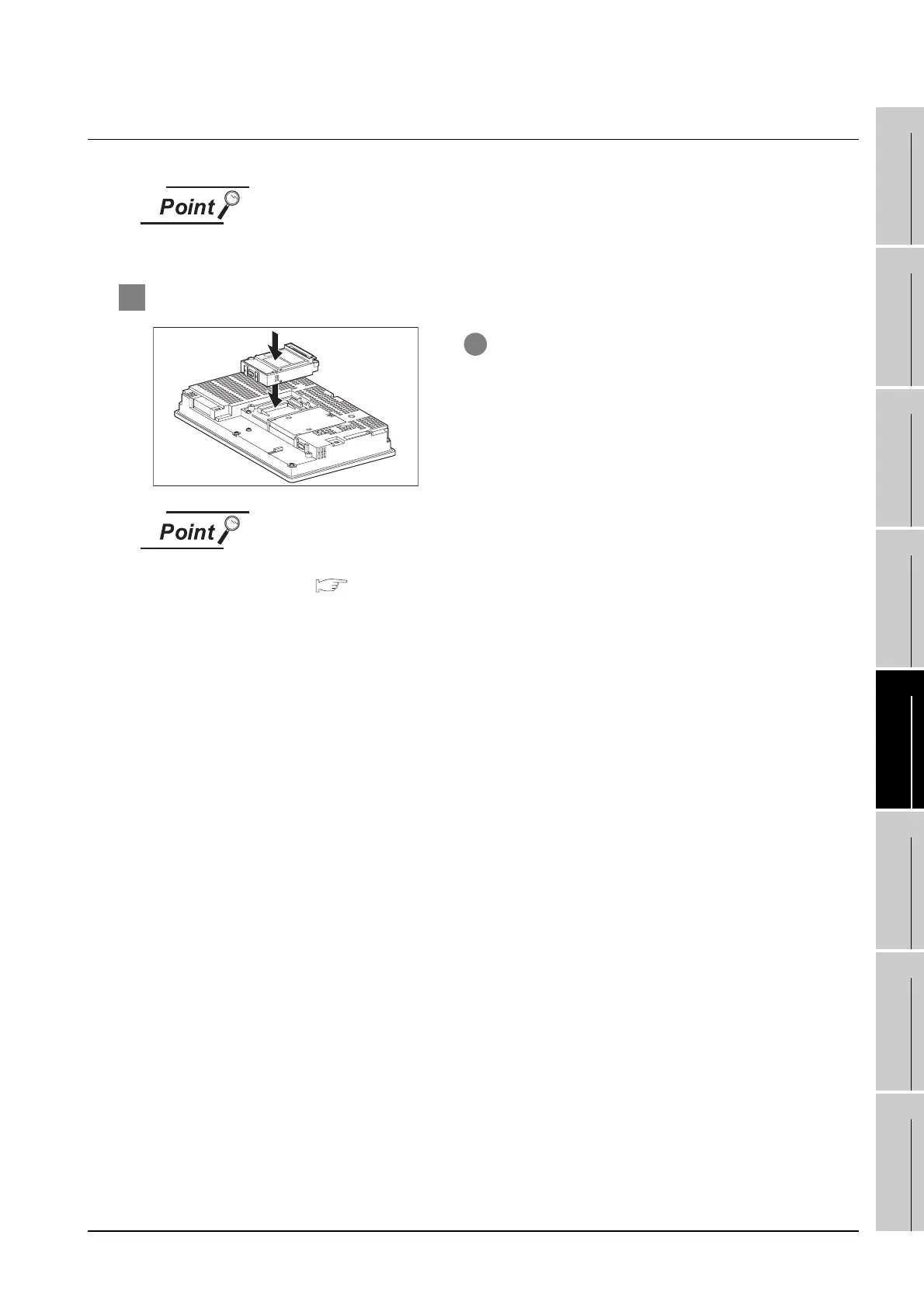
1 Attaching the communication unit
Serial communication units
For details on the serial communication units, refer to the following manual:
GT15 Serial Communication Unit User’s Manual
GT15-RS2, GT15-RS4, GT15-RS4-TE
1 Attach the serial communication unit to the
extension unit connector on the GOT.

 Loading...


