3 - 18
3.2 Connection Cable
3.2.1 RS-232 cable
3.2 Connection Cable
The RS-232 cable used for connecting the GOT to the FX PLC can be prepared by the user.
The following provides connection diagrams for each cable, connector specifications and other information.
3.2.1 RS-232 cable
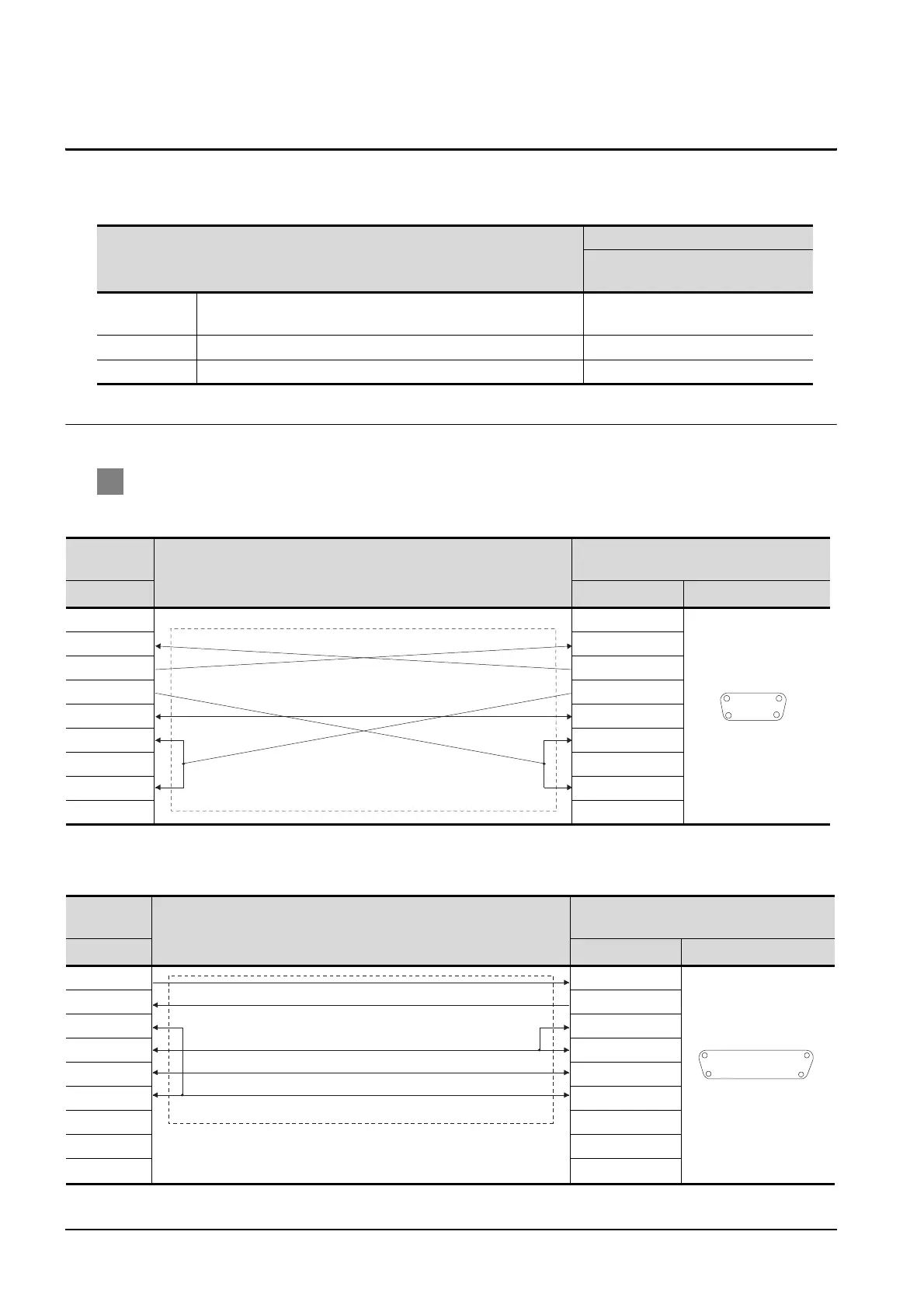
1 Connection diagram
(1) RS-232cable 1)
*1 The pin layput shows the engagement face.
(2) RS-232cable 2)
*1 The pin layput shows the engagement face.
Model name
Connection cable
RS-232 cable
(Refer to Section 3.2.1)
Function
expansion board
FX1N-232-BD, FX2N-232-BD,FX3U-232-BD RS-232cable 1)
Function adapter
FX2NC-232ADP,FX3U-232ADP, CFX3U-485ADP
RS-232cable 1)
Function adapter FX0N-232ADP RS-232cable 2)
GOT Side
Cable connection
FX PLC side
(Dsub9 pin)
PIN No. PIN No.
Pin layout
*1
1 1
2 2
3 3
4 4
5 5
6 6
7 7
8 8
9 9
GOT Side
Cable connection
FX PLC side
(Dsub25pin)
PIN No. PIN No.
Pin layout
*1
2 2
3 3
8 5
4 6
5 7
6 20
1 5
6 9
D-SUB 9 pins:female
D-SUB 25 pins:female
113
14
25
 Loading...


