8 - 20
8.3 PLC Side Setting
8.3.1 Connecting to Ethernet module (Q Series)
8.3 PLC Side Setting
8.3.1 Connecting to Ethernet module (Q Series)
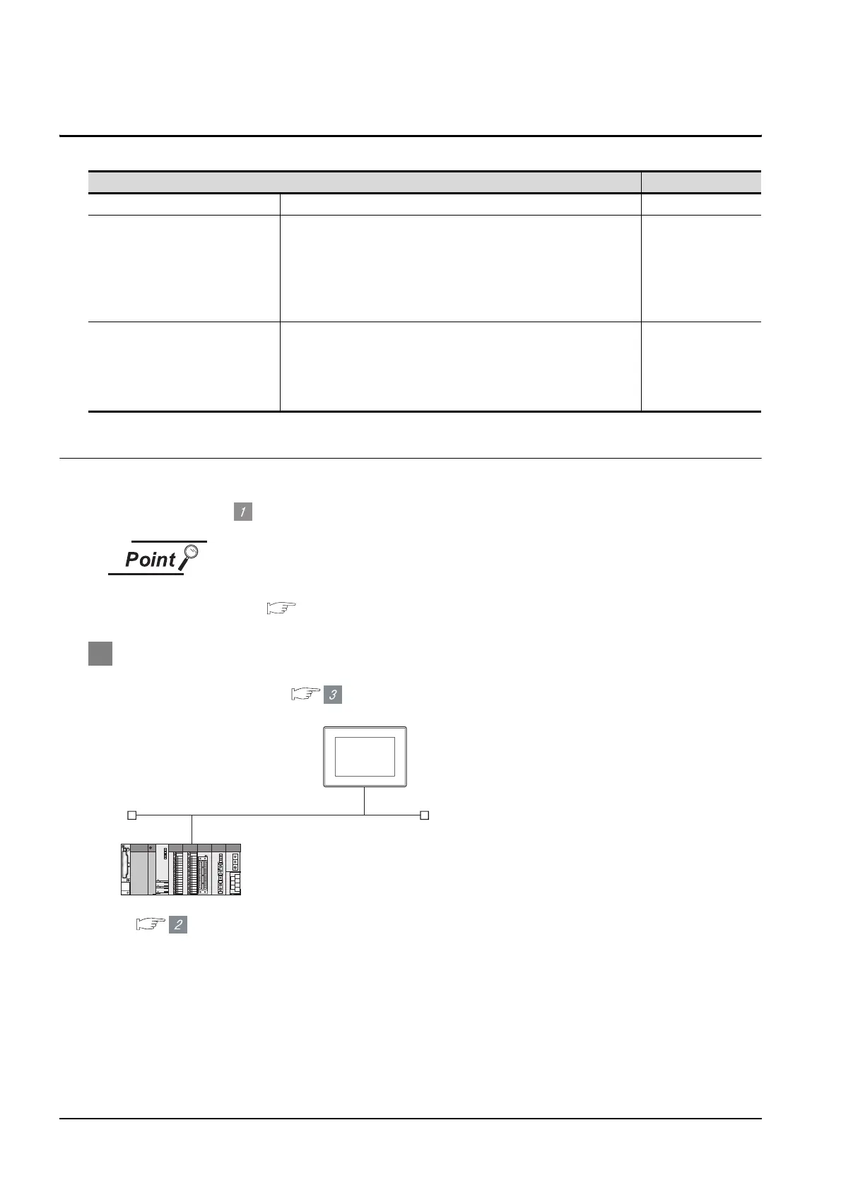
This section describes the settings of the GOT and Ethernet module (Q Series) given for the system
configuration shown at .
Ethernet module (Q Series)
For details of the Ethernet module (Q Series), refer to the following manual.
Q Corresponding Ethernet Interface Module User's Manual (Basic)
1 System configuration
*1 The Ethernet module is mounted on the base unit slot 0.
The Start I/O No. of the Ethernet module is set to "0".
Model Reference
Ethernet module (Q Series) QJ71E71-100, QJ71E71-B5, QJ71E71-B2, QJ71E71 Section 8.3.1
Ethernet module (QnA Series)
AJ71QE71N3-T, AJ71QE71N-B5, AJ71QE71N-B2,
AJ71QE71N-T, AJ71QE71N-B5T,
AJ71QE71, AJ71QE71-B5,
A1SJ71QE71N3-T, A1SJ71QE71N-B5, A1SJ71QE71N-B2,
A1SJ71QE71N-T, A1SJ71QE71N-B5T,
A1SJ71QE71-B5, A1SJ71QE71-B2
Section 8.3.2
Ethernet module (A Series)
AJ71E71N3-T, AJ71E71N-B5, AJ71E71N-B2,
AJ71E71N-T, AJ71E71N-B5T, AJ71E71-S3,
A1SJ71E71N3-T, A1SJ71E71N-B5, A1SJ71E71N-B2,
A1SJ71E71N-T, A1SJ71E71N-B5T,
A1SJ71E71-B5-S3, A1SJ71E71-B2-S3
Section 8.3.3
[Network parameter] of GX Developer
<GOT> (The settings other than the
following are set to the default)
*1
2
3
Network No.
PC No.
IP address
Port No.
Communication format
: 1
: 1
: 192.168.0.18
: 5001
: UDP (fixed)
Network No.
PC No.
IP address
Port No.
Communication format
: 1
: 2
: 192.168.0.19
: 5001
: UDP(fixed)
<Ethernet module> (The settings other than the following are
set to the default)
[Communication settings] and [Ethernet setting] of GT
Designer2
 Loading...


