14 - 2
14.1 System Configuration
14.1.1 Connecting to FP0-C16CT or FP0-C32CT
14.1 System Configuration
Select a system configuration suitable for your application.
Conventions used in this section
Numbers (e.g. ) of System configuration and connection conditions correspond
to the numbers (e.g. ) of System equipment.
Use these numbers as references when confirming models and applications.
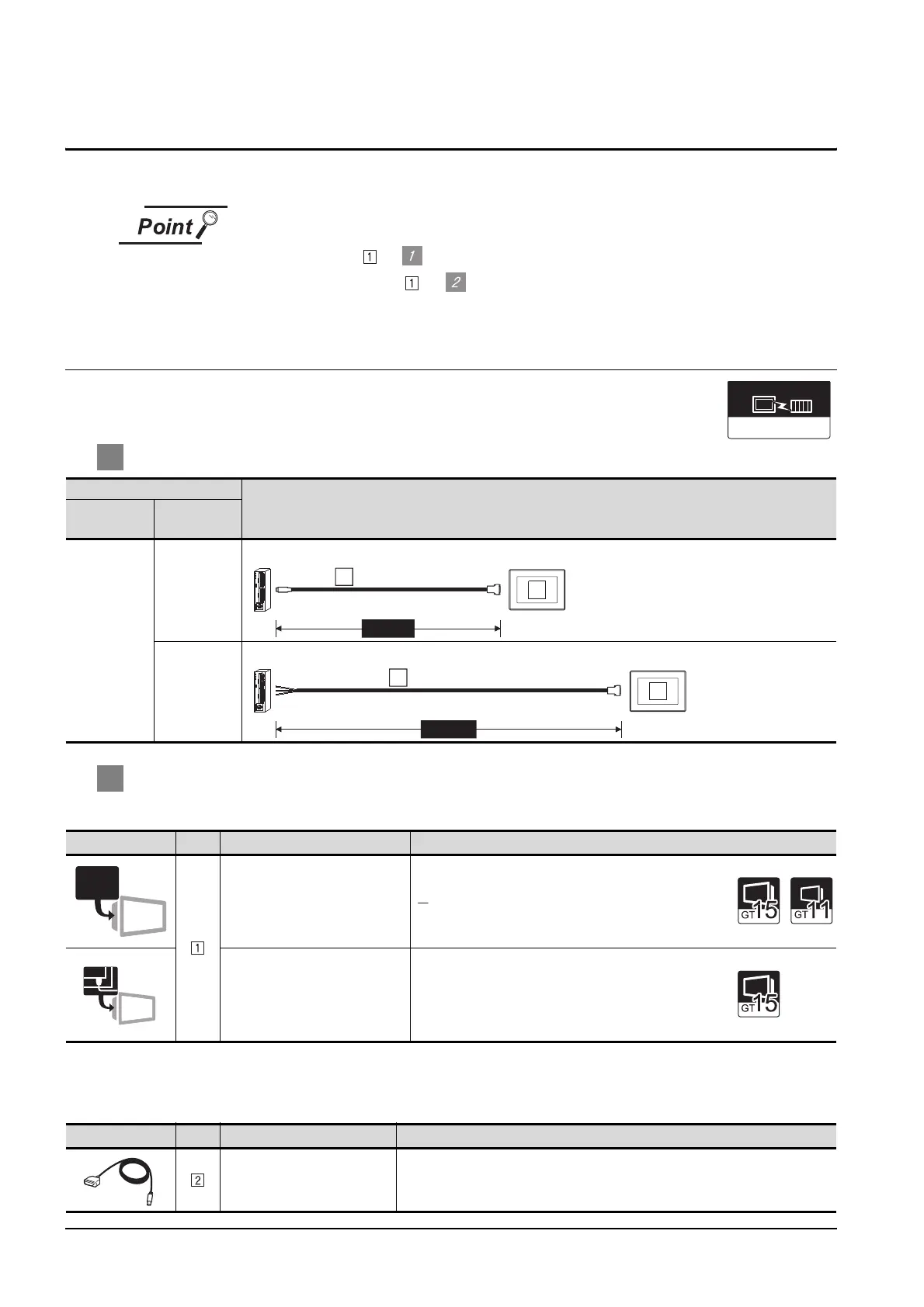
14.1.1 Connecting to FP0-C16CT or FP0-C32CT
1 System configuration and connection conditions
2 System equipment
(1) GOT
(2)
(3) Cable
Connection conditions
System configuration
Number of
GOTs
Distance
1
3m or less
15m or less
Image No. Name Model name
RS-232 interface
• For RS-232 communication
(Built into GOT)
RS-232 Communication Unit
• For RS-232 communication
GT15-RS2-9P
Image No. Name Model name
RS-232 cable
• Between tool port of PLC
CPU and GOT
AFC8503(3m)
MATSUSHITA
MEWNET-FP
Communication driver
MAX3m
RS-232 cable
2
Connect to the tool port.
1
MAX15m
RS-232 cable 4)
3
Connect to the RS232C port.
1
RS-232
RS-232
 Loading...


