29 - 16
29.4 Preparatory Procedure for Accessing
29.4.4 Accessing the PLC by the GX Developer
2 When connecting the GOT and PC with USB
(1) When the Q/QnA/ACPU, motion controller CPU (A Series) is connected
The following is an access example by GX Developer (When connected to the A Series) when the
GOT and PC are connected by USB.
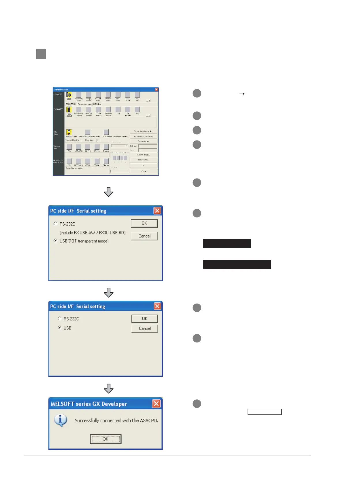
1 Click [Online] [Read from PLC] in GX
Developer.
2 Set the [PLC Series] to [ACPU].
3 The [Connection Setup] is displayed.
4 Set the [Connection Setup]:
PC side I/F : Serial
PLC side I/F : PLC module
Other station : No specification
5 Double-click [PLC module] of the PLC
side I/F to display [PLC side IF Detailed
setting of PLC module].
6 Check-mark either of the following in
[PLC side IF Detailed setting of PLC
module].
[via GOT (Bus) transparent mode]
[via GOT (direct coupled) transparent
mode]
7 Return to [Transfer Setup] and double-
click [Serial] of the PC side I/F to display
[PC side I/F Serial setting].
8 Select [USB] in [PC side I/F Serial
setting].
9 The screen returns to the [Connection
Setup]. Click the to check
if GX Developer has been connected to
the ACPU.
Bus connection
Direct CPU connection
connection test

 Loading...


