24.4 Setting on Servo Amplifier Side
24.4.3 Connecting to the MELSERVO-J3 series
24 - 31
17
CONNECTION TO
ALLEN-BRADLEY PLC
18
CONNECTION TO
SIEMENS PLC
19
MICROCOMPUTER
CONNECTION
20
CONNECTION TO OMRON
TEMPERATURE
CONTROLLER
21
CONNECTION TO
YAMATAKE TEMPERATURE
CONTROLLER
22
CONNECTION TO RKC
TEMPERATURE
CONTROLLER
23
CONNECTION TO
FREQROL SERIES
INVERTER
24
SERVO AMPLIFIER
CONNECTION
24.4.3 Connecting to the MELSERVO-J3 series
MELSERVO-J3 series
For details of the MELSERVO-J3 series, refer to the following manual.
See the technical manual for the MELSERVO-J3 series servo amplifiers.
1 Parameters of MELSERVO-J3 series
Enter the parameters of the MELSERVO-J3 series.
*1 Avoid duplication of the station No. with any of the other axes.
*2 Specify the same transmission speed as that of the GOT.
For the transmission speed setting method of the GOT, refer to the following.
See Section 24.3.3 Setting communication interface (Communication settings)
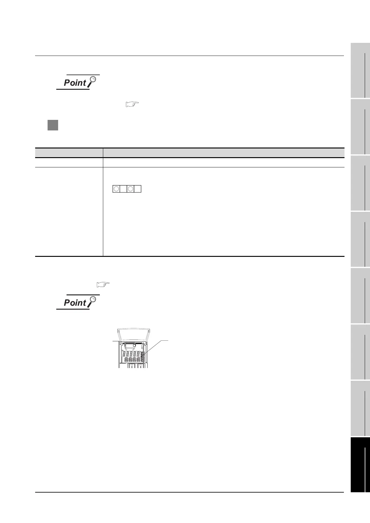
(1) Parameter setting
Set the parameter at the pushbutton switch provided on the operation section of
the servo amplifier or setup software.
(2) When changing the parameter
Turn off then on the servo amplifier to be effective the new parameter.
Item Setting
Basic parameter No. PC20 Station No. setting: 0 to 31 <Default: 0> (*1)
Basic parameter No. PC21
Serial communication function selection <Default: 0000>
(1) Serial communication baud rate selection (*2)
0: 9600bps
1: 19200bps
2: 38400bps
3: 57600bps
(2) Communication response delay time selection
0: Invalid
1: Valid (Response after 800µs or longer delay)
2 1
Basic parameter No. PC21
MODE UP DOWN
SET
Pushbutton switch provided on
the operation section of the servo amplifie
 Loading...


