31.1 System Configuration
31 - 3
25
BAR CODE READER
CONNECTION
26
PRINTER CONNECTION
27
CNC CONNECTION
28
MULTI-CHANNEL
FUNCTION
29
FA TRANSPARENT
FUNCTION
30
MULTIPLE-GT11
CONNECTION FUNCTION
31
GATEWAY FUNCTION INDEX
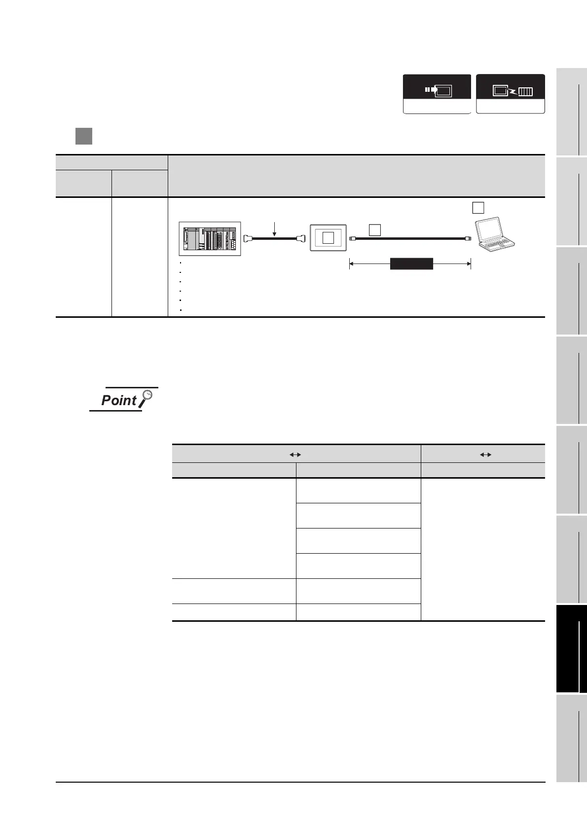
1 System configuration and connection conditions
*1 Includes the GOT (server function), the GOT (client function) and the PC used for communication with the GOT.
*2 The destination connected with the twisted pair cable varies with the configuration of the applicable Ethernet
network system.
Connect to the Ethernet module, hub, transceiver or other system equipment corresponding to the applicable
Ethernet network system.
PLC connection type and communication interface
The PLC connection types and the communication interfaces for systems using the
gateway function are shown below.
*1 Connect the PLC to the same Ethernet communication unit as that used for connection between the
GOT and PC.
Ethernet connection is available between the GOT or PC that uses the gateway function and the PLC
within the same network. (Two or more Ethernet communication units may not be installed at the same
time.)
Connection conditions
System configuration
Number of
GOTs*1
Distance
64 (max.)
Within 100m
(max.)
PLC GOT GOT PC
Connection type Communication interface of GOT Communication interface of GOT
• Direct CPU connection
• Computer link connection
• Third party PLC connection
• Microcomputer connection
• Temperature controller
connection
RS-232 interface
Ethernet communication units
RS-422 conversion unit
RS-232 communication unit
RS-422/485 communication unit
BUS connection BUS connection unit
• Ethernet connection
Ethernet communication unit
*1
Connection type
dependent
Communication driver
Gateway
Option OS
Direct CPU connection
Computer link connection
Ethernet connection
Third party PLC connection
Microcomputer connection
Temperature controller connection
Twisted pair cable
Varies according to
the connection type.
1
MAX100m
*2
PC
3
2
 Loading...


