4.4 PLC Side Setting
4.4.1 Connecting serial communication module (Q Series)
4 - 41
1
OVERVIEW
2
BUS CONNECTION
3
DIRECT CONNECTION
TO CPU
4
COMPUTER LINK
CONNECTION
5
MELSECNET/10
CONNECTION (PLC TO
PLC NETWORK)
6
CC-Link CONNECTION
(INTELLIGENT DEVICE
STATION)
7
CC-Link CONNECTION
(Via G4)
8
ETHERNET
CONNECTION
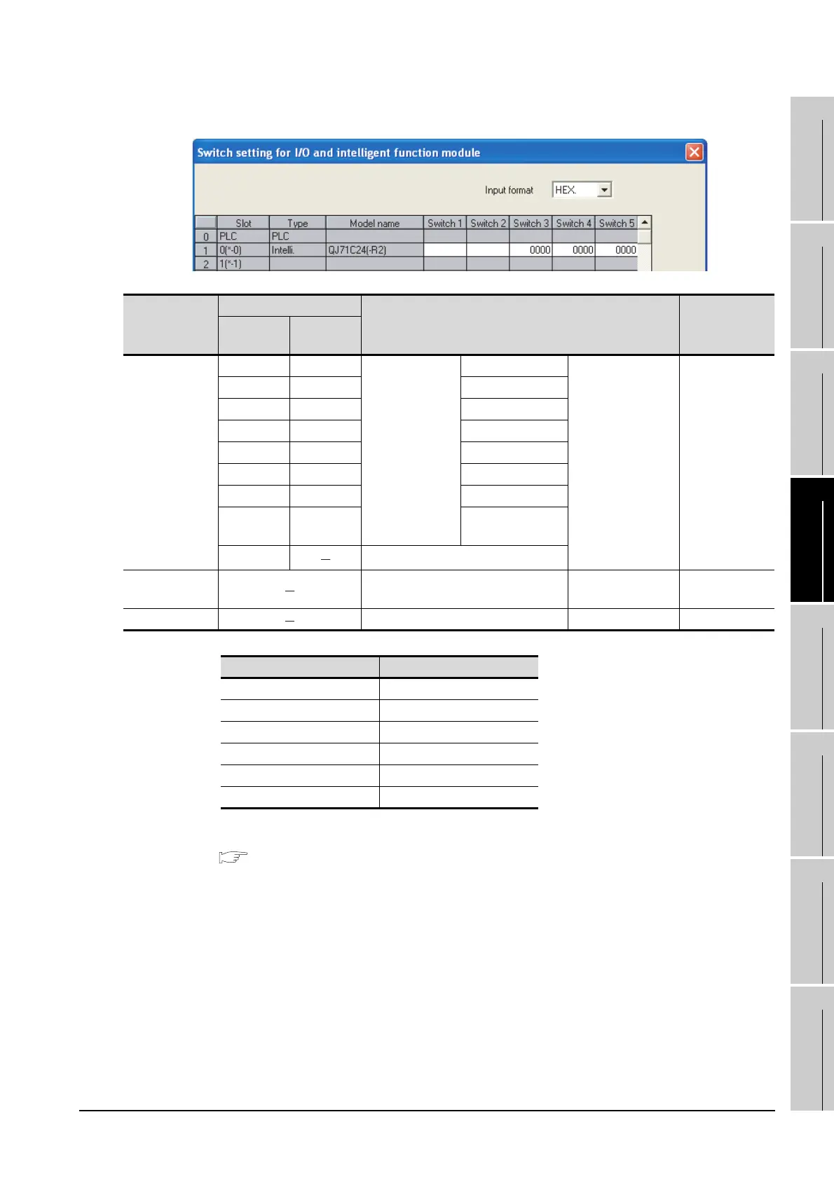
(2) When connecting to the CH2 side
*1 The module operates under the following transmission specifications.
*2 The serial communication module operates at the transmission speed set on the GOT.
For details on the transmission speed setting on the GOT side, refer to the following.
Section 4.3.3 Setting communication interface (Communication settings)
Switch No.
Bit
Description Setting
Position
Specified
value
Switch 3
b0 OFF
CH2 transmission
setting
*1
Operation setting
(Operates according
to the GOT side
specifications.)
0000H
b1 OFF Data bit
b2 OFF Parity bit
b3 OFF Even/odd parity
b4 OFF Stop bit
b5 OFF Sum check code
b6 OFF Write during RUN
b7 OFF
Setting
modifications
b8 to b15
CH2 transmission speed setting
*2
Switch 4 CH2 Communication protocol setting
GX Developer
connection
0000H
Switch 5 Station number setting 0th station 0000H
Transmission specifications Setting details
Operatiom setting Independent
Data bit 8 bits
Parity bit Yes
Even/odd parity Odd
Stop bit 1 bit
Sum check code Yes

 Loading...


