5.2 Preparatory Procedures for Monitoring
5.2.7 Checking for normal monitoring
5 - 23
1
OVERVIEW
2
BUS CONNECTION
3
DIRECT CONNECTION
TO CPU
4
COMPUTER LINK
CONNECTION
5
MELSECNET/10
CONNECTION (PLC TO
PLC NETWORK)
6
CC-Link CONNECTION
(INTELLIGENT DEVICE
STATION)
7
CC-Link CONNECTION
(Via G4)
8
ETHERNET
CONNECTION
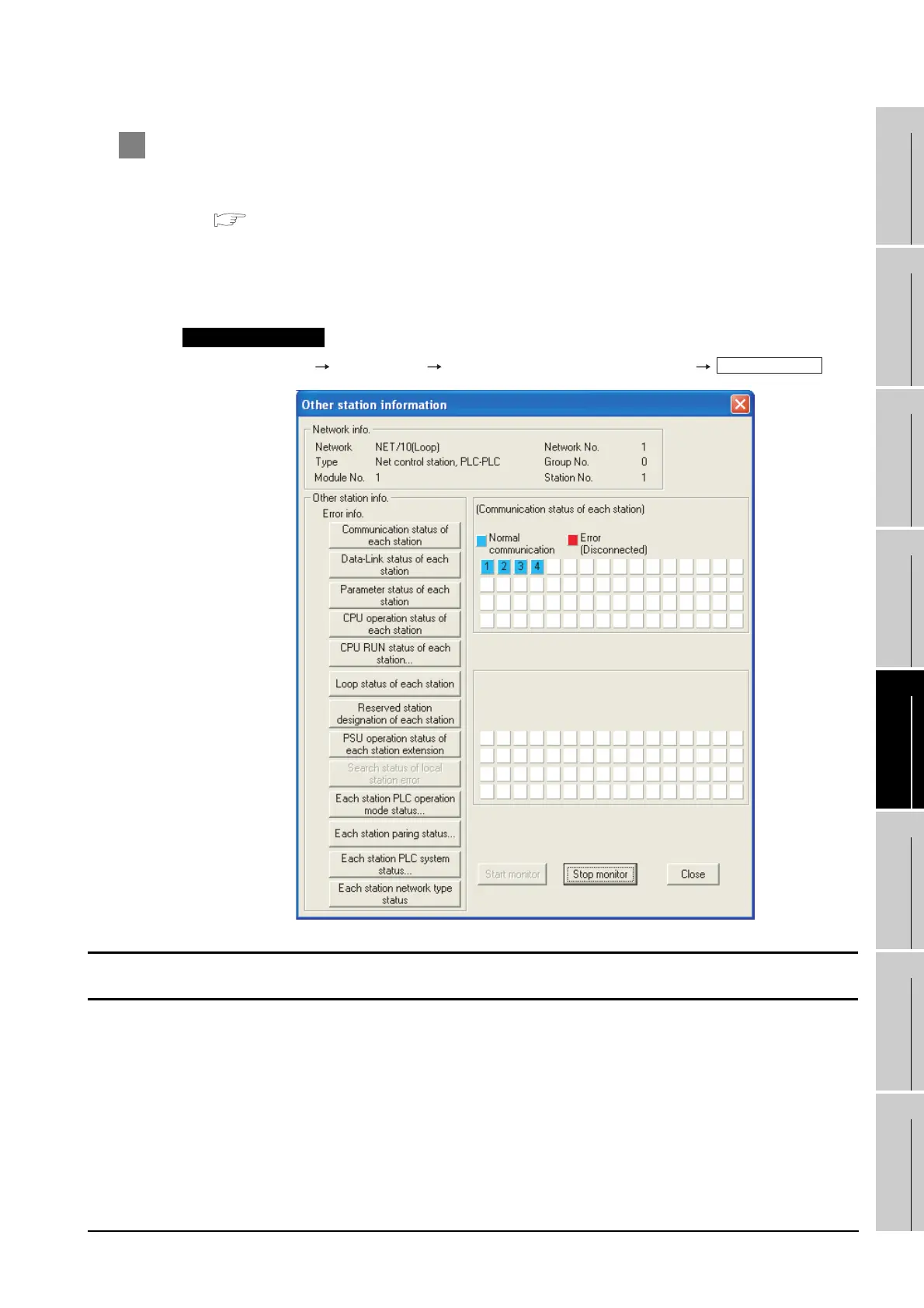
4 Checking if the GOT is performed the data link correctly
Check if the GOT is performed the data link correctly in [Other station info.].
For the GX Developer operation method, refer to the following manual.
Q corresponding MELSECNET/H Network System Reference Manual (PLC to PLC
network)
(1) Check [Communication status of each station] and [Data-Link status of each station]. (The display
example on GX Developer Version 8)
GX Developer [Diagnostics] [MELSECNET (II)/10/H diagnostics]
Startup procedure
All settings related to communications are complete now.
Create screens on GT Designer2 and download the project data again.
Other station info.

 Loading...


