8.3 PLC Side Setting
8.3.3 Connecting to Ethernet module (A Series)
8 - 31
1
OVERVIEW
2
BUS CONNECTION
3
DIRECT CONNECTION
TO CPU
4
COMPUTER LINK
CONNECTION
5
MELSECNET/10
CONNECTION (PLC TO
PLC NETWORK)
6
CC-Link CONNECTION
(INTELLIGENT DEVICE
STATION)
7
CC-Link CONNECTION
(Via G4)
8
ETHERNET
CONNECTION
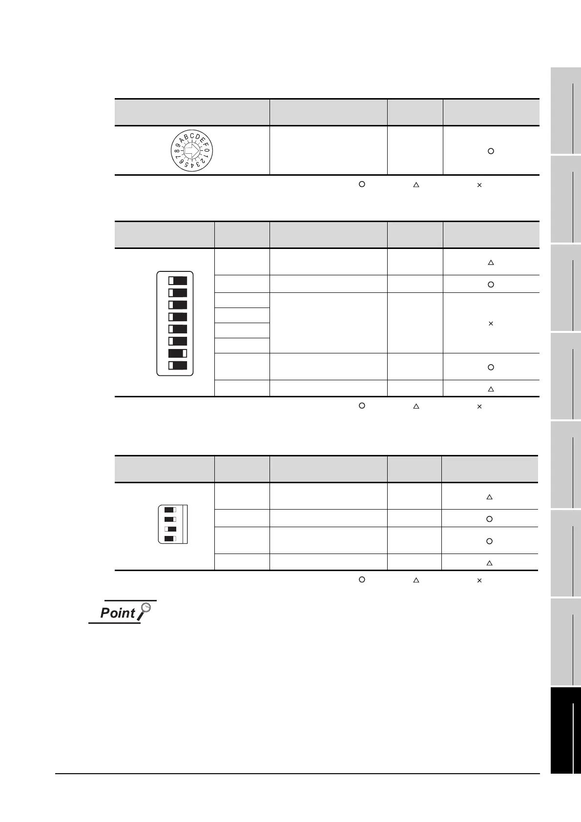
(1) Operation mode setting switch
: Necessary : As necessary : Not necessary
(2) Exchange condition setting switch
*1
: Necessary : As necessary : Not necessary
*1 The exchange condition setting switches of A1SJ71E71-B5-S3 and A1SJ71E71-B2-S3 are specified as the
below.
: Necessary : As necessary : Not necessary
When the switch setting has been changed
Turn the PLC CPU OFF then ON again, or reset the PLC CPU.
Operation mode setting switch Description Setting
Setting necessity at GOT
connection
Online 0(fixed)
Exchange condition setting
switch
Setting switch Description Setting
Setting necessity at GOT
connection
SW1
Selection of line processing at
TCP timeout error
OFF
SW2 Data code setting (binary code) OFF(fixed)
SW3
Must not to be used OFF(fixed)
SW4
SW5
SW6
SW7
CPU exchange timing setting
(Enable write at RUN time)
ON(fixed)
SW8 Initial timing setting OFF
Exchange condition setting
switch
Setting switch Discription Setting
Setting necessity at GOT
connection
SW1
Selection of line processing at
TCP timeout error
OFF
SW2 Data code setting (binary code) OFF(fixed)
SW3
CPU exchange timing setting
(Enable write at RUN time)
ON(fixed)
SW4 Initial timing setting OFF
SW1
SW2
SW3
SW4
SW5
SW6
SW7
SW8
OFF ON
SW1
SW2
SW3
SW4
OFFON

 Loading...


