1 - 3
1
OVERVIEW
2
BUS CONNECTION
3
DIRECT CONNECTION
TO CPU
4
COMPUTER LINK
CONNECTION
5
MELSECNET/10
CONNECTION (PLC TO
PLC NETWORK)
6
CC-Link CONNECTION
(INTELLIGENT DEVICE
STATION)
7
CC-Link CONNECTION
(Via G4)
8
ETHERNET
CONNECTION
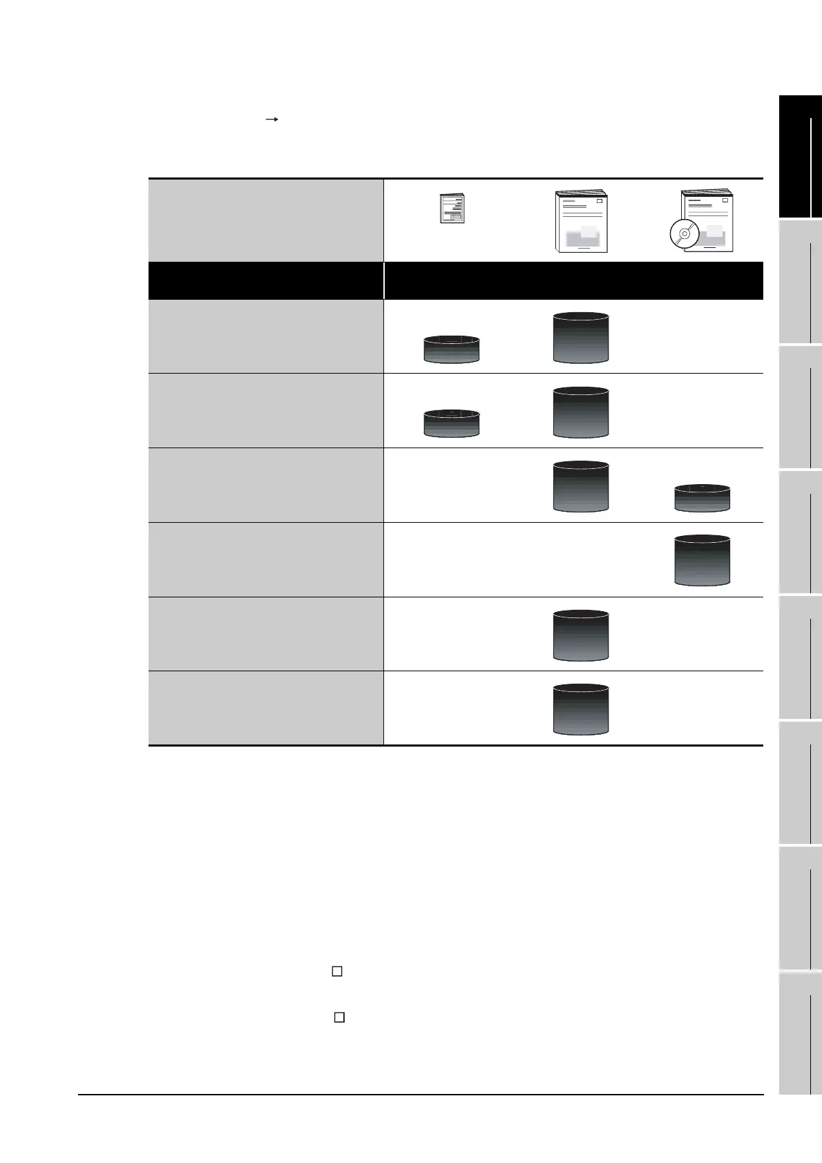
(2) Installing a GOT Connecting with a PLC
For the operations from installing a GOT to communicating with a PLC CPU, refer to the following
manuals.
*1 Stored in the GT Works2/GT Designer2 in PDF format.
(3) Other manuals
The following manuals are also available.
The following manuals are stored in the GT Works2/GT Designer2 in PDF format.
(a) GOT1000 Series Extended/Option Functions Manual
Describes how to use the ladder monitoring function, system monitor function and list editor for
A/F, network monitor function, Q motion monitor function, servo amplifier monitor function,
CNC monitor function, intelligent module monitor function.
(b) GOT1000 Series Gateway Functions Manual
Describes how to use the gateway function.
(c) GT Simulator2 Version Operating Manual
Describes how to simulate the created project data with the GT Simulator2.
(d) GT Converter2 Version Operating Manual
Describes how to use the GT Converter2.
(Included)
Purpose
GT15 General Description
GT11 General Description
GT15 User's Manual
GT11 User's Manual
GOT1000 Series
Connection Manual
*1
Confirming part names and
specifications of the GOT
Confirming the GOT installation method
Confirming the mounting method for
communication units or option devices
Confirming the PLC connection method
Confirming the utility operation method
Confirming error codes (system alarm)
displayed on GOT
Overview
Detailed
Overview
Detailed
Detailed
Overview
Detailed
Detailed
Detailed

 Loading...


