9 - 46
9.4 PLC Side Setting
9.4.5 Connecting rack type host link unit
(4) Setting DIP switches
(5) Setting the CTS switch
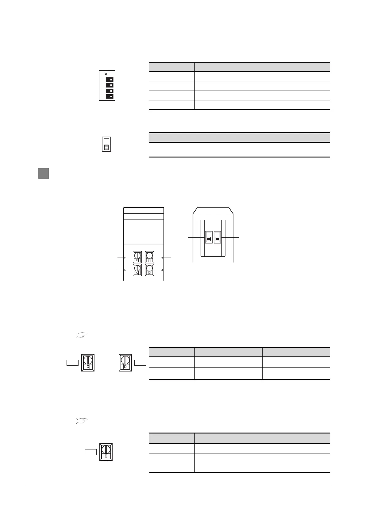
2 Switch setting on C200H-LK202-V1
Set the switches accordingly.
(1) Setting Machine No. (SW1, SW2)
Set the Machine No. within the range of 00 to 31.
Set the Machine No. according to the Host Address setting on the GOT side.
For the Host Address setting on the GOT side, refer to the following.
Section 9.3.3 Setting communication interface (Communication settings)
(2) Setting transmission speed (SW3)
Set the same transmission speed as that of the GOT side.
For the transmission speed setting on the GOT side, refer to the following.
Section 9.3.3 Setting communication interface (Communication settings)
*1 Only transmission speeds available on the GOT side are shown.
Switch No. Setting
1OFF
2OFF
3 ON (1:N procedure)
4 OFF (no 5V power supply)
Setting
0V
Rotary switch Description Setting
SW1
Machine No. upper digit (x10
1
)
0 to 3
SW2
Machine No. lower digit (x10
0
)
0 to 9
Setting
*1
Setting
4 4800bps
5 9600bps
6 19200bps
1 2 3 4
ON
LK201-V1
RUN
RCV
XM
ERROR
SW1 SW2
SW3
SW4
Front Rear
(4)
(1)
(3)
(1)
(2)
(5)
SW1
SW2
SW3

 Loading...


