13.2 Connection Cable
13.2.1 RS-232 cable
13 - 7
9
CONNECTION TO
OMRON PLC
10
CONNECTION TO
KEYENCE PLC
11
CONNECTION TO
SHARP PLC
12
CONNECTION TO
TOSHIBA PLC
13
CONNECTION TO
HIATACHI PLC
14
CONNECTION TO
MATSUSHITA PLC
15
CONNECTION TO
YASKAWA PLC
16
CONNECTION TO
YOKOGAWA PLC
13.2.1 RS-232 cable
The following shows the connection diagrams and connector specifications of the RS-232 cable used for
connecting the GOT to a PLC.
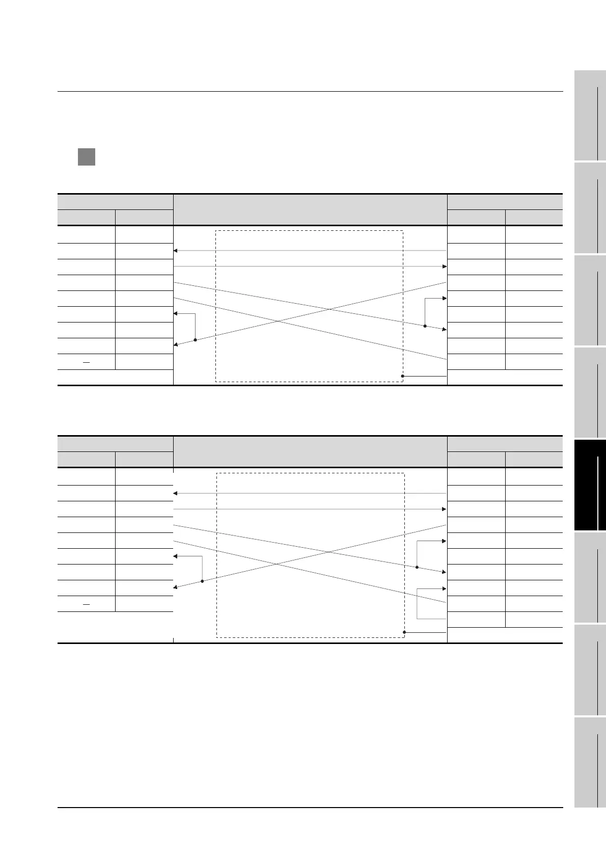
1 Connection diagram
(1) RS-232 cable 1)
*1 GT15: CD, GT11: NC
(2) RS-232 cable 2)
*2 GT15: CD, GT11: NC
GOT side
Cable connection and signal direction
HITACHI product side
Signal name Pin No. Pin No. Signal name
CD/NC
*1
1 1NC
RD(RXD) 2 2SD
SD(TXD) 3 3RD
ER(DTR) 4 4RS
SG 5 5CS
DR(DSR) 6 6RV1(ER)
RS(RTS) 7 7RV2(DR)
CS(CTS) 8 8PHL
9 9SG
FG
GOT side
Cable connection and signal direction
HITACHI product side
Signal name Pin No. Pin No. Signal name
CD/NC
*2
1 1NC
RD(RXD) 2 2SD
SD(TXD) 3 3RD
ER(DTR) 4 4RS
SG 5 5CS
DR(DSR) 6 6RV1(ER)
RS(RTS) 7 7RV2(DR)
CS(CTS) 8 8PHL
9 9SG
14 ER
FG

 Loading...


