2 - 4
2.1 System Configuration
2.1.1 Connecting to QCPU (Q mode)
Bus extension connector box
When installing the 1st GOT 13.2m or more away from the main base unit, the bus
extension connector box is required.
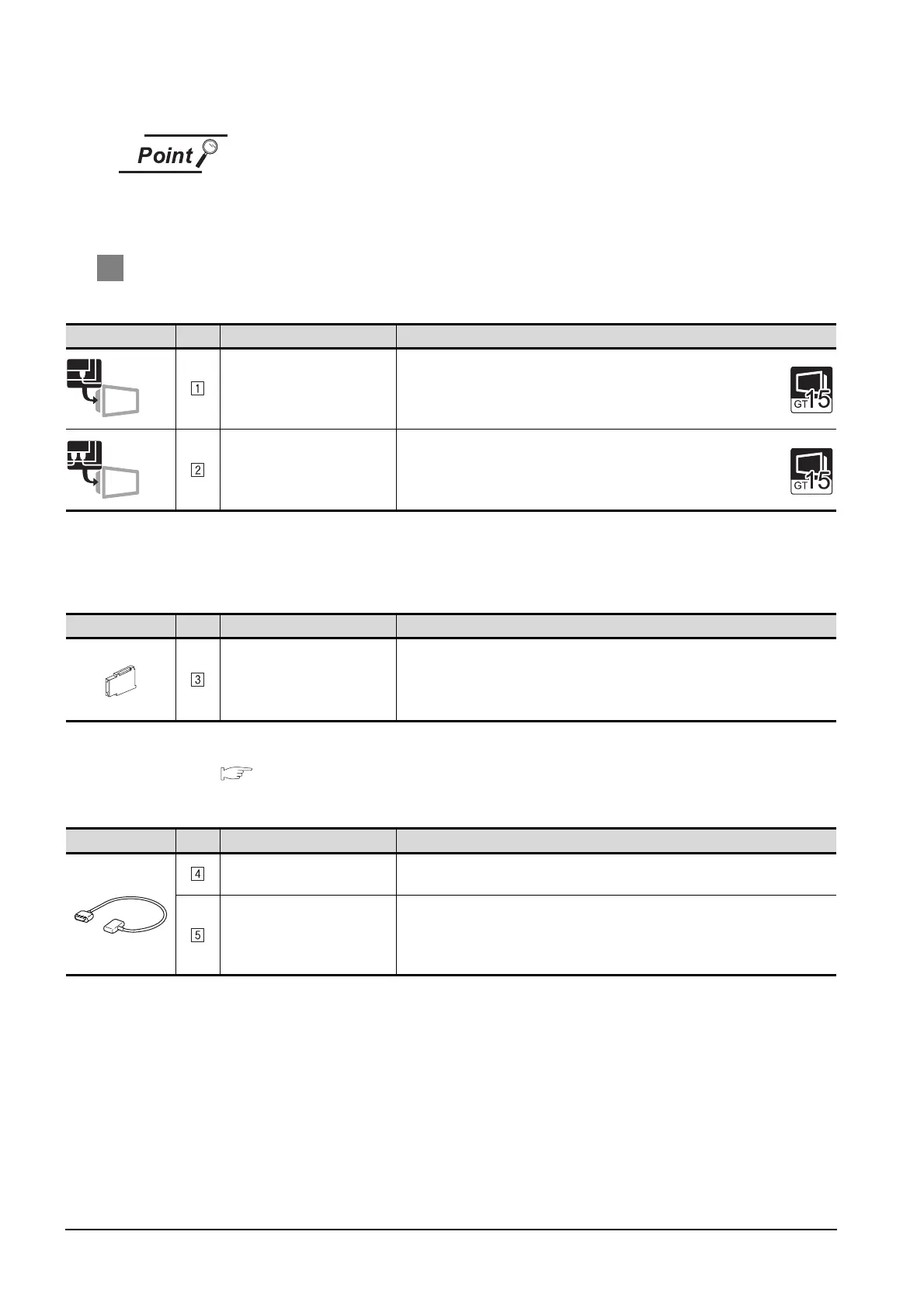
2 System equipment
(1) GOT
*1 About the bus connection unit
GT15-75QBUSL,
GT15-QBUS: Used for a terminal GOT. (Not available for an intermediary GOT.)
GT15-75QBUS2L,
GT15-QBUS2: Used for an intermediary GOT. (Can be used for a terminal GOT.)
(2) PLC
*2 Set the bus extension connector box to the same Stage No. as that of the GOT unit.
For details on the Stage No. setting, refer to the following.
Section 2.2.3 Setting communication interface (Communication settings)
(3) Cable
Image No. Name Model name
Bus connection unit
*1
• For terminal GOT
GT15-75QBUSL, GT15-75QBUS2L, GT15-QBUS, GT15-QBUS2
Bus connection unit
*1
• For intermediary GOT
GT15-75QBUS2L, GT15-QBUS2
Image No. Name Model name
Bus extension connector box
*2
• Unit used for extending
distance between GOT and
base unit
A9GT-QCNB
Image No. Name Model name
Connection cable
• Between base unit and GOT
GT15-QC06B(0.6m), GT15-QC12B(1.2m), GT15-QC30B(3m),
GT15-QC50B(5m), GT15-QC100B(10m)
Connection cable
• Between bus extension
connector box and GOT
• Between GOTs
GT15-QC06B(0.6m), GT15-QC12B(1.2m), GT15-QC30B(3m),
GT15-QC50B(5m), GT15-QC100B(10m),
GT15-QC150BS(15m), GT15-QC200BS(20m), GT15-QC250BS(25m),
GT15-QC300BS(30m), GT15-QC350BS(35m)
Terminal
Intermediary

 Loading...


