2.1 System Configuration
2.1.2 Connecting to QnACPU or AnCPU type
2 - 7
1
OVERVIEW
2
BUS CONNECTION
3
DIRECT CONNECTION
TO CPU
4
COMPUTER LINK
CONNECTION
5
MELSECNET/10
CONNECTION (PLC TO
PLC NETWORK)
6
CC-Link CONNECTION
(INTELLIGENT DEVICE
STATION)
7
CC-Link CONNECTION
(Via G4)
8
ETHERNET
CONNECTION
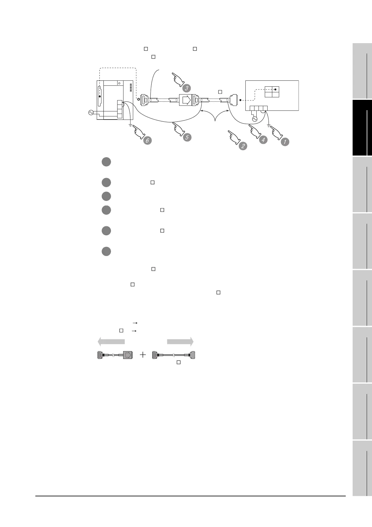
*3 When using GT15-C EXSS-1 or GT15-C BS, perform the grounding in the following steps.
(1) When using GT15-C EXSS-1
(2) When using GT15-C BS
Follow the GOT side grounding steps in (1) above for both GOTs.
*4 About GT15-C EXSS-1
• It is composed of GT15-EXCNB (0.5m) and GT15-C BS (10 to 30m).
• Calculate the cable length based on GT15-C100EXSS-1 (10m), GT15-C200EXSS-1 (20m) and GT15-
C300EXSS-1 (30m).
• Connect the connectors as follows:
GX15-EXCNB PLC CPU side
GT15-C BS GOT side
1 Connect the LG and FG terminals of the terminal block on the GOT unit power and ground them
with a cable.
2 Use the GT15-C BS's FG cable of 28cm or less.
3 Do not connect the GT15-EXCNB's FG ground cable.
4 Connect the GT15-C BS's FG cable on the GOT side to FG of the GOT unit power's terminal
block.
5 Connect the GT15-C BS's FG cable on the PLC side to FG of the
PLC's power supply module.
6 Connect the LG and FG terminals of the terminal block on the PLC
7 and ground them with a cable.
FG
LG
N
L
(GT15-EXCNB)
GOT
OUT IN
FG
LG
NL
(GT15-C BS)
PLC
Not connected
2SQ cables to
FG terminals,
28cm or less
(GT15-EXCNB) (GT15-C
BS)
PLC side GOT side

 Loading...


