16.4 PLC Side Setting
16.4.1 Connecting CPU port/D-sub 9-pin conversion cable
16 - 29
9
CONNECTION TO
OMRON PLC
10
CONNECTION TO
KEYENCE PLC
11
CONNECTION TO
SHARP PLC
12
CONNECTION TO
TOSHIBA PLC
13
CONNECTION TO
HITACHI PLC
14
CONNECTION TO
MATSUHSHITA PLC
15
CONNECTION TO
YASKAWA PLC
16
CONNECTION TO
YOKOGAWA PLC
16.4.1 Connecting CPU port/D-sub 9-pin conversion cable
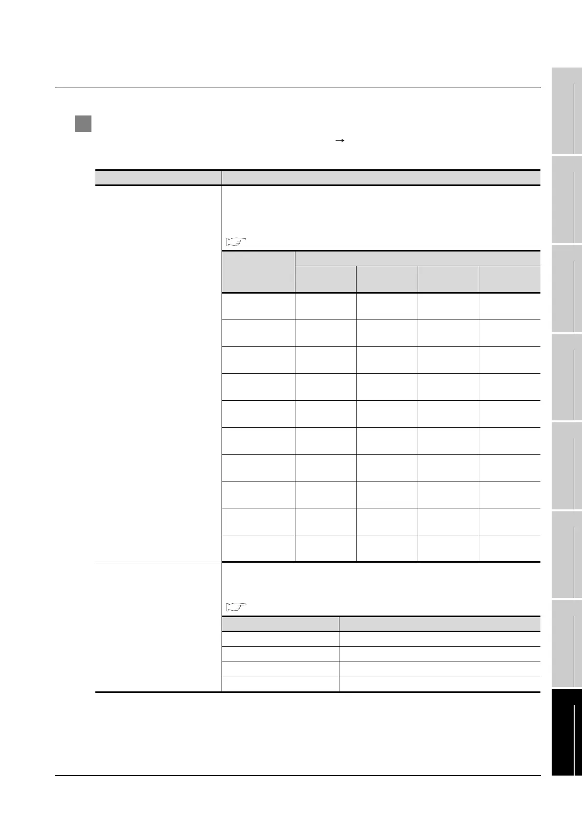
1 Setting of PLC CPU
Make the PLC CPU settings, displaying [Configuration] [Communication setting] with the program
development tool or the ladder-programming tool.
*1 The communication mode that can be selected differs according to the CPU.
Item Setting
Communication mode
*1
Set the communication mode of the CPU (transmission speed and data format).
Set the transmission speed and data format according to settings of the transmission speed,
data length, parity and stop bit on the GOT side.
For details on these GOT side settings, refer to the following.
Section 16.3.3 Setting communication interface (Communication settings)
Item
Transmission speed and data format
Transmission
speed
Data length Parity Stop bit
Communication
mode 0
9600bps 8 bits Even 1 bit
Communication
mode 1
9600bps 8 bits None 1 bit
Communication
mode 2
19200bps 8 bits Even 1 bit
Communication
mode 3
19200bps 8 bits None 1 bit
Communication
mode 4
38400bps 8 bits Even 1 bit
Communication
mode 5
38400bps 8 bits None 1 bit
Communication
mode 6
57600bps 8 bits Even 1 bit
Communication
mode 7
57600bps 8 bits None 1 bit
Communication
mode 8
115200bps 8 bits Even 1 bit
Communication
mode 9
115200bps 8 bits None 1 bit
CPU PC link function settings
Set the following when using the CPU programming port as the PC link function.
Make the checksum setting according to the sum check setting on the GOT side.
For the sum check setting on the GOT side, refer to the following.
Section 16.3.3 Setting communication interface (Communication settings)
Item Setting
Use of PC link function Mark. (Use enabled)
Checksum Mark. (ON) Do not mark. (OFF)
End character Do not mark. (OFF)
Protect function Do not mark. (OFF)

 Loading...


