2 - 18
2.1 System Configuration
2.1.6 Connecting to motion controller CPU (A273UCPU, A273UHCPU(-S3), A373UCPU(-S3))
2 System equipment
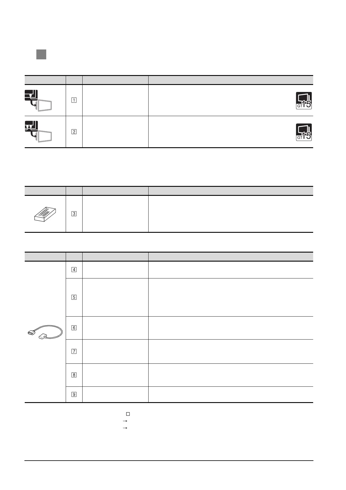
(1) GOT
*1 About the bus connection unit
GT15-75ABUSL, GT15-ABUS: Used for a terminal GOT. (Not available for an intermediary GOT.)
GT15-75ABUS2L, GT15-ABUS2: Used for an intermediary GOT. (Can be used for a terminal GOT.)
(2) PLC
(3) Cable
*2 GT15-C100EXSS (10m), GT15-C200EXSS (20m) or GT15-C300EXSS (30m) can be also used.
Connect the GT15-C EXSS connectors as follows:
Connector [COM1] PLC CPU side
Connector [COM2] GOT side
Image No. Name Model name
Bus connection unit
*1
• For terminal GOT
GT15-75ABUSL, GT15-75ABUS2L, GT15-ABUS
GT15-ABUS2
Bus connection unit
*1
• For intermediary GOT
GT15-75ABUS2L, GT15-ABUS2
Image No. Name Model name
Bus connector conversion box
• Unit used for converting
connection cable connector
and extending distance
between GOT and base unit
A7GT-CNB
Image No. Name Model name
Connection cable
*5
• Between base unit and GOT
GT15-A370C12B-S1(1.2m), GT15-A370C25B-S1(2.5m)
Connection cable
*5
• Between base unit and GOT
• Between base unit and bus
connector conversion box
• Between base units
GT15-A370C12B(1.2m), GT15-A370C25B(2.5m)
Connection cable
• Between base unit and bus
connector conversion box
GT15-AC06B(0.6m), GT15-AC12B(1.2m), GT15-AC30B(3m),
GT15-AC50B(5m)
Connection cable
*2*3*4
• Between bus connector
conversion box and GOT
GT15-C100EXSS-1(10m), GT15-C200EXSS-1(20m),
GT15-C300EXSS-1(30m)
Connection cable
*3
• Between GOTs
GT15-C07BS(0.7m), GT15-C12BS(1.2m), GT15-C30BS(3m),
GT15-C50BS(5m), GT15-C100BS(10m), GT15-C200BS(20m),
GT15-C300BS(30m)
Connection cable
• Between base unit and GOT
GT15-C12NB(1.2m), GT15-C30NB(3m), GT15-C50NB(5m)
Terminal
Intermediary

 Loading...


