19.1 Microcomputer Connection
19 - 3
17
CONNECTION TO
ALLEN-BRADLEY PLC
18
CONNECTION TO
SIEMENS PLC
19
MICROCOMPUTER
CONNECTION
20
CONNECTION TO OMRON
TEMPERATURE
CONTROLLER
21
CONNECTION TO
YAMATAKE TEMPERATURE
CONTROLLER
22
CONNECTION TO RKC
TEMPERATURE
CONTROLLER
23
CONNECTION TO
FREQROL SERIES
INVERTER
24
SERVO AMPLIFIER
CONNECTION
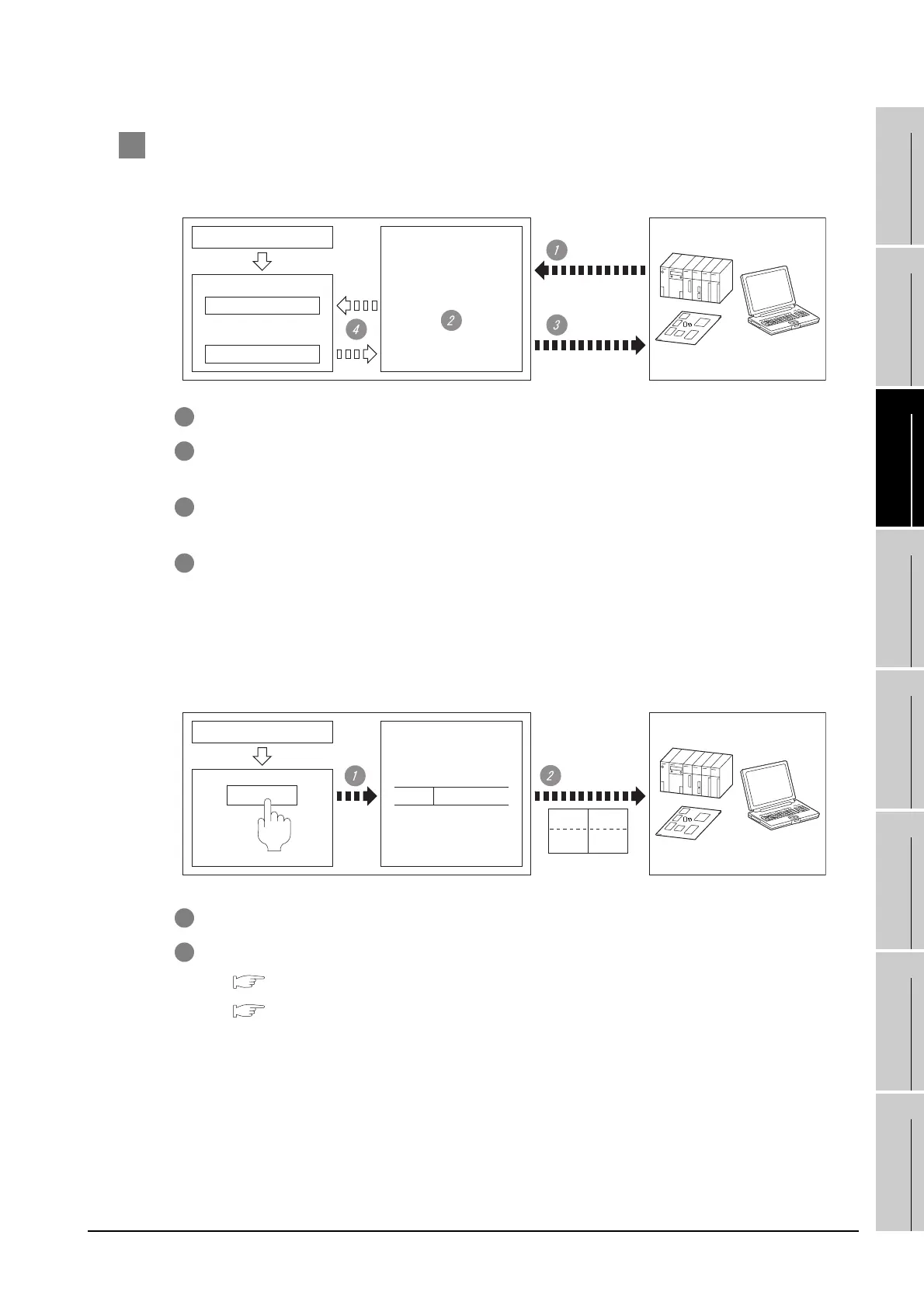
1 Flow of data processing
(1) When reading or writing data
1 The host sends a request message (the read/write command) to the GOT.
2 The GOT performs a read/write processing to its virtual devices according to the request from the
host.
3 Upon completion of the processing, the GOT sends a response message (processing result) to
the host.
4 Creating the following objects on the screen allows you to use the data read/written to the virtual
devices:
• Numerical Display that displays data written by the write command
• Numerical Input that is used to input data to be upload to the host
(2) When outputting interrupts
1 Data are written to the virtual devices for interrupt output from the touch switches on the GOT.
2 The GOT sends the written data (interrupt output) to the host.
*1 Section 19.5 Message Formats
*2 Section 19.4 Device Data Area
Host
Display (D4 to 9)
Input (D20)
GOT
Screen data
04/06/01 18:46:49
1254
Screen
display
Device data area
(virtual devices)
*2
Request
message
*1
Response
message
*1
HostGOT
Screen data
Interrupt
output
*1
Screen
display
Device data area
(virtual devices)
*2
Interrupt (D13)
D13 3139H
31H
Output
value 1
Output
value 2
39H
(when the number of
interrupt data bytes is 2)

 Loading...


