19 - 22
19.4 Device Data Area
19.4.6 SM devices
(1) About the side where virtual devices are set
System: Set on the system side.
User: Set on the user side (by sending request messages from host or
using the touch switches, etc. on the GOT).
(2) About interrupt outputs (SM0 to 49)
• To disable the interrupt output, turn ON SM52 (interrupt code output disable
flag). ( Section 19.4.6 SM devices)
• To enable the interrupt output, set 8 bits to the data length at "Communication
Detail Settings". ( Section 19.6.3 Setting communication interface
(Communication settings))
• When "7 bits" is set, the MSB (8th bit) is ignored. (Example: FF
H 7FH)
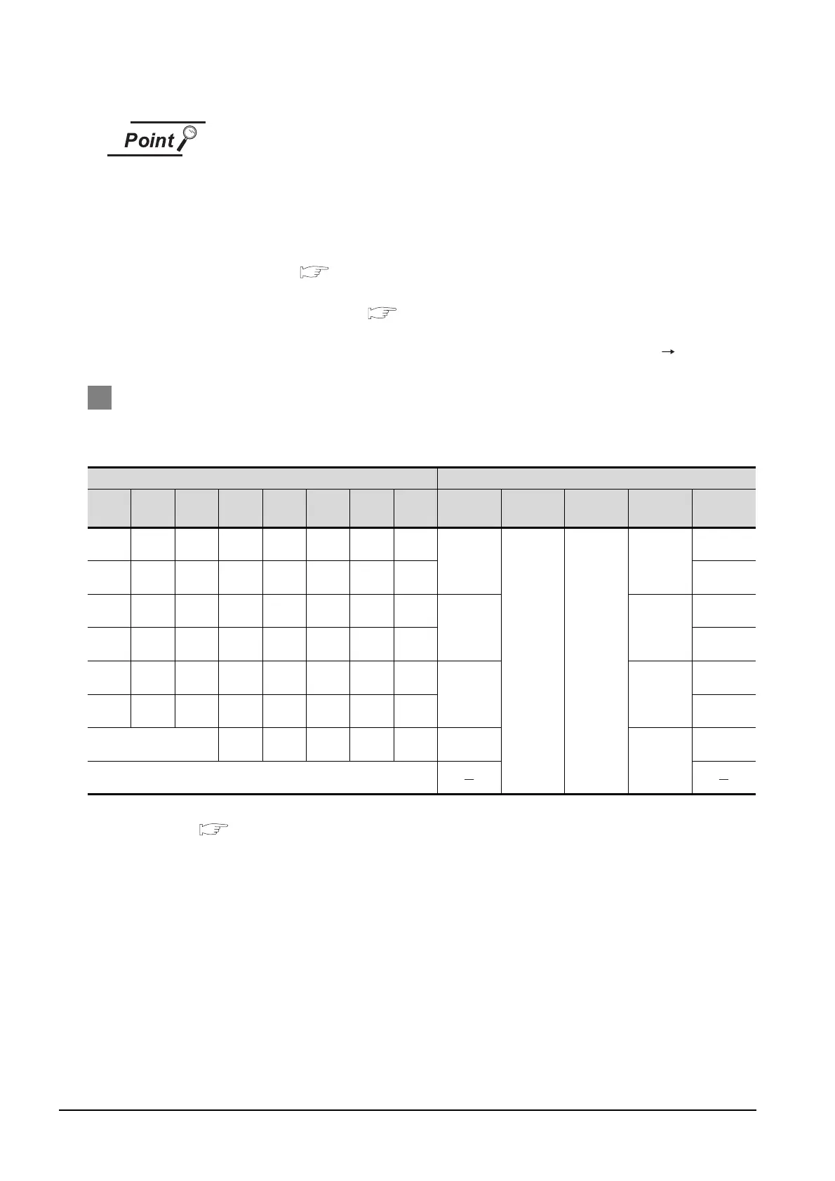
2 Differences in address specifications by data format
The address specification of devices varies depending on the data format.
*1
The following shows the address specification values for each data format.
*1 For the address specification method for each data format, refer to the following.
Section 19.5 Message Formats
• Formats 1, 2 : GOT-A900 Series microcomputer connection
• Formats 3 to 6 : A compatible 1C frame
• Formats 7 to 10 : QnA compatible 3C/4C frame
• Formats 11 to 13 : Digital Electronics Corporation's memory link method
• Formats 14, 15 : GOT-F900 Series microcomputer connection
*2 In formats 3 to 6, values are specified within a range of M9000 to 9052.
*3 In formats 7 to 10, values are specified within a range of SM0 to 52.
*4 For reading or writing data in word units, specify the addresses in 16-point units. (Example: SM0, SM16, SM32,
etc.)
Address Address Specification Value
b7 b6 b5 b4 b3 b2 b1 b0
Formats
1, 2
Formats
3 to 6
Formats
7 to 10
Formats
11 to 13
Formats
14, 15
SM7 SM6 SM5 SM4 SM3 SM2 SM1 SM0
8464
*2*4 *3*4
2110H
2200H
SM15 SM14 SM13 SM12 SM11 SM10 SM9 SM8 2201H
SM23 SM22 SM21 SM20 SM19 SM18 SM17 SM16
8465 2111H
2202H
SM31 SM30 SM29 SM28 SM27 SM26 SM25 SM24 2203H
SM39 SM38 SM37 SM36 SM35 SM34 SM33 SM32
8466 2112H
2204H
SM47 SM46 SM45 SM44 SM43 SM42 SM41 SM40 2205H
Unused SM52 SM51 SM50 SM49 SM48 8467
2113H
2206H
Unused
 Loading...


