19 - 88
19.7 System Configuration Examples
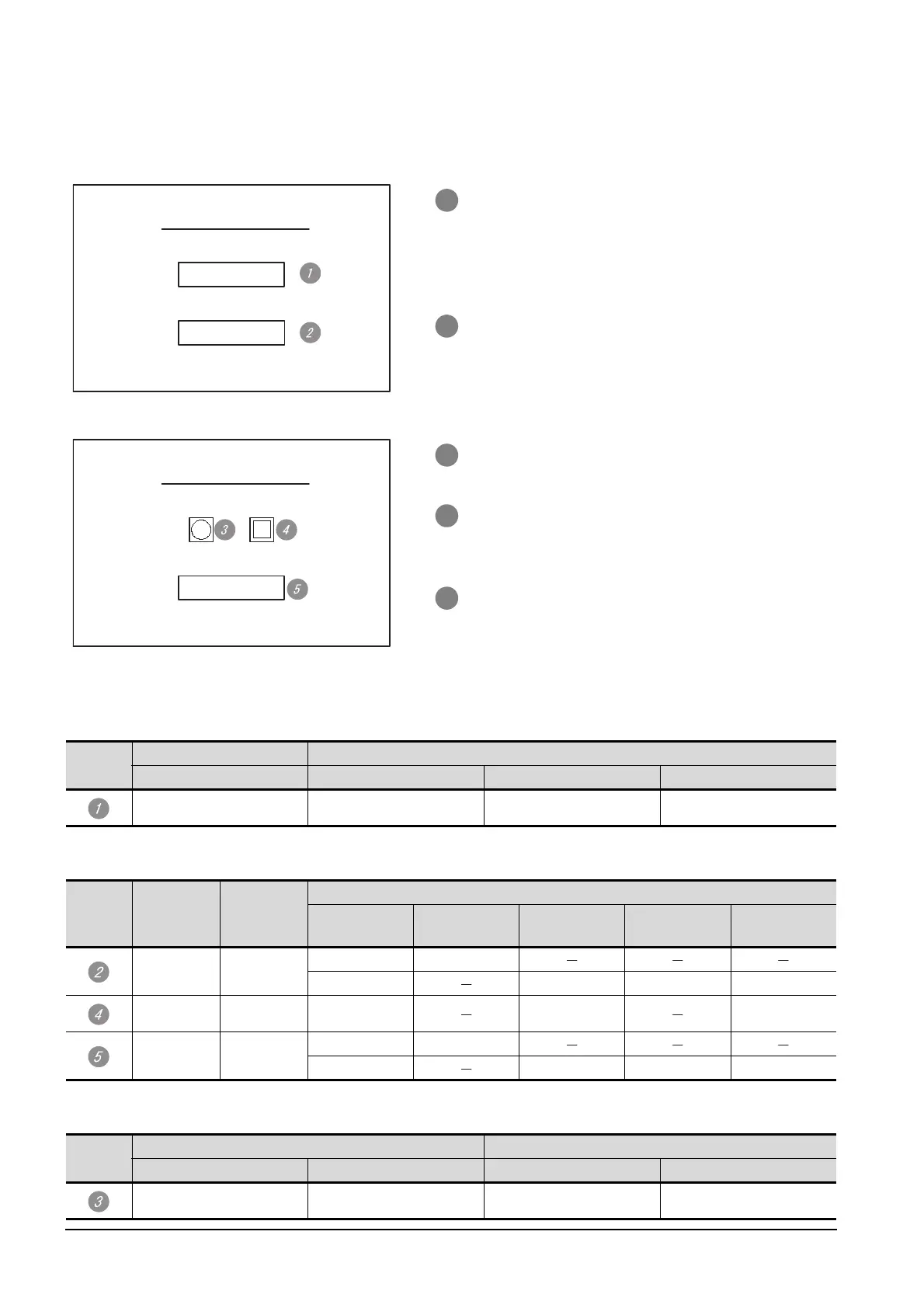
(b) Monitor screen image
Create the following screens by GT Designer2.
Numerical value display function
Touch switch function
Lamp display function
Base screen 1
1 Numerical value display function
By setting this with the numerical value display
function, the device value of D21 can be monitored.
The device value is incremented only while "Sample
Screen 1" is displayed.
2 Touch switch 1
This is the screen switching switch to "Sample
Screen 2". Touching this changes the base screen to
"Sample Screen 2".
Base screen 2
3 Lamp display function
The device status of D22.b0 is displayed as a lamp.
4 Touch switch 2
This is an alternate switch for changing the state of
D22.b0.
5 Touch switch 3
This is the screen switching switch to "Sample
Screen 1".
Touching this changes the base screen to "Sample
Screen 1".
No.
Basic setting Display settings
Device Display format Display size Number of display digits
D21, unsigned binary, 16 bits Unsigned 16 bits Arbitrary 4
No. Basic setting Display setting
Operation setting
Action
Switch
destination
Device Data format Action type
Arbitrary Arbitrary
Base switching Fixed value 2
Word D13 Signed binary Fixed value 01
Arbitrary Arbitrary Bit D22.b0 Bit ALT
Arbitrary Arbitrary
Base switching Fixed value 1
Word D13 Signed binary Fixed value 255
No.
Basic setting Display method (bit)
Device Graphic ON OFF
D22.b0, bit Basic figure Arbitrary Arbitrary
Sample Screen 1
123
Screen 2
Sample Screen 2
Screen 1

 Loading...


