19 - 90
19.7 System Configuration Examples
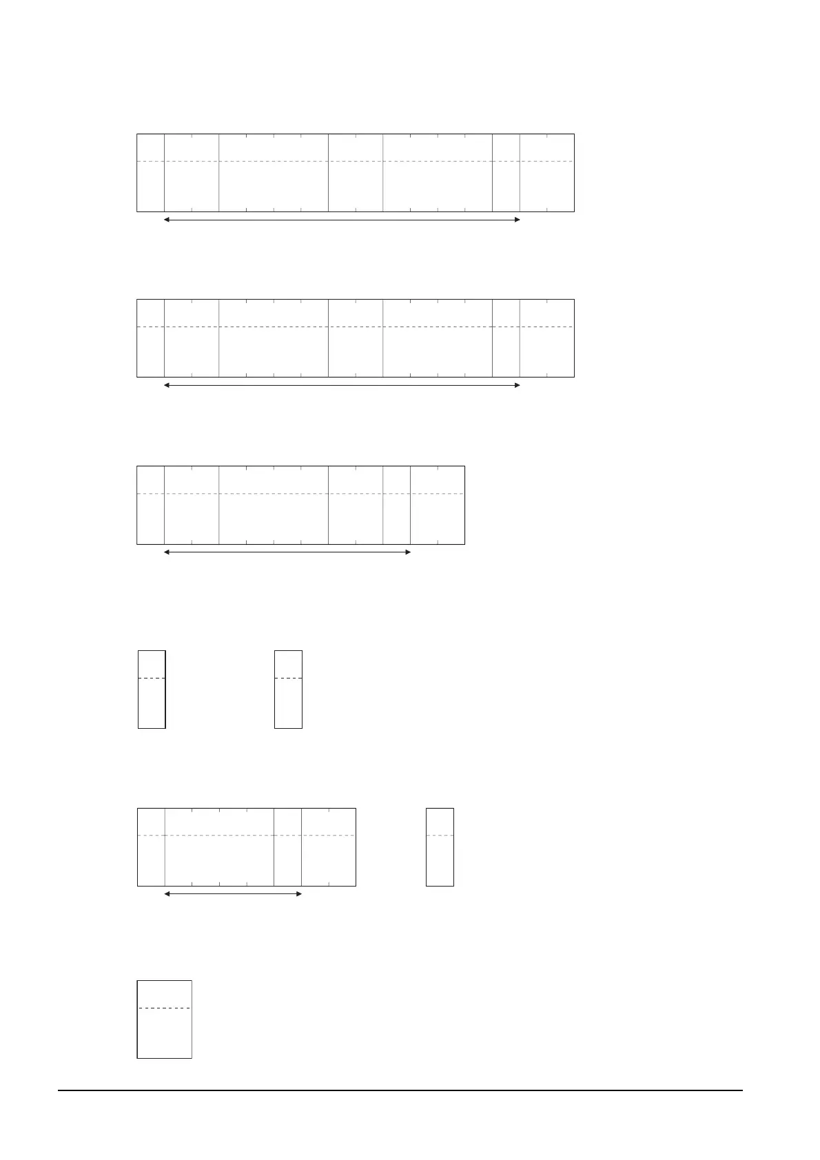
*1 Displays the send packet structure of the screen 1 batch switching write packet.
*2 Displays the send packet structure of the numerical value display batch write packet.
*3 Displays the send packet structure of the numerical value display batch read packet.
*4 Displays the receive packet structure of the batch write response packet.
*5 Displays the receive packet structure of the batch read response packet.
*6 Displays the receive packet structure of the interrupt receive packet.
Sum check is performed in this range.
02
H
STX
03
H
ETX
(H) (L)
82
38
H 32H
Sum
Check
(H) (L)
Command
WD
57
H 44H
(H) (L)
Address
02
30
H 32H
––
0
30
H
0
30
H
(H) (L)
Number of
points
01
30
H 31H
(H) (L)
Data 1 (D20)
00
30
H 30H
––
1
31
H
0
30
H
Sum check is performed in this range.
02
H
STX
03
H
ETX
(H) (L)
Sum check
(Changes
according to
data section.)
(H) (L)
Command
WD
57
H 44H
(H) (L)
Address
02
30
H 32H
––
1
31H
0
30
H
(H) (L)
Number of
points
01
30H 31H
(H) (L)
Data 1 (D21)
––
(any value)
Sum check is performed in this range.
02
H
STX
03
H
ETX
(H) (L)
BD
42
H 44H
Sum
Check
(H) (L)
Command
RD
52
H 44H
(H) (L)
Address
01
30
H 31H
––
2
32
H
(H) (L)
Number of
points
01
30
H 31H
0
30
H
15H
NAK
When an error occurred
06H
ACK
When normally operated
Sum check is performed in this range.
02
H
STX
03
H
ETX
(H) (L)
Sum check
(Changes
according to
data section.)
(H) (L)––
Data
(any data)
When normally operated
15H
NAK
When an error occurred
Output value
Interrupt data
(value of D13)

 Loading...


