EasyManuals Logo

Mitsubishi GOT1000 Series User Manual

Mitsubishi GOT1000 Series
1216 pages
To Next Page IconTo Next Page
To Previous Page IconTo Previous Page
Page #872 background imageLoading...
Page #872 background image
21 - 16
21.2 Connection Cable
21.2.1 RS-232 cable
(2) RS-232 cable 2)
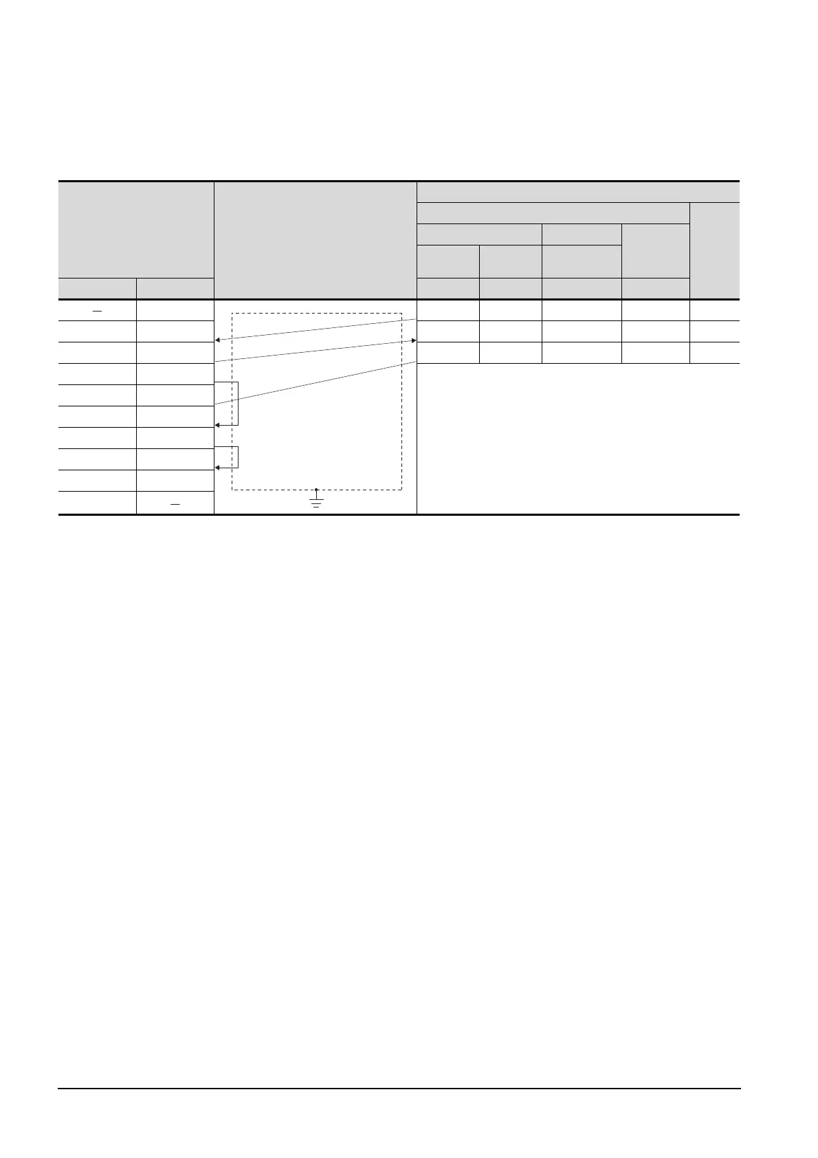
Pin No. of temperature controller differs depending on model and optional function model. Refer to
the following table. The numbers in ( ) of the following table correspond to optional function models.
GOT side
Cable connection and signal direction
YAMATAKE product side
Model of temperature controller
Signal
name
SDC20 SDC21 SDC40A
SDC40B
SDC40G
(03, 05) (10) (04, 07, 09)
Signal name Pin No. Pin No. Pin No. Pin No. Pin No.
1 17 16 27 60 SD
RD(RXD) 2 18 17 28 59 RD
SD(TXD) 3 5 5 29 61 SG
ER(DTR) 4
SG 5
DR(DSR) 6
RS(RTS) 7
CS(CTS) 8
NC 9
FG

Table of Contents

Questions and Answers:

Question and Answer IconNeed help?

Do you have a question about the Mitsubishi GOT1000 Series and is the answer not in the manual?

Mitsubishi GOT1000 Series Specifications

General IconGeneral
Power Supply24 VDC
TypeHMI (Human Machine Interface)
SeriesGOT1000
Resolution640 x 480 pixels
Touch Panel TypeResistive
InterfaceRS-232, USB
Storage Temperature-20 to 60°C
Protection RatingIP65
Display TypeTFT LCD
Brightness400 cd/m²
Backlight Life50, 000 hours
CPURISC
Shock Resistance147 m/s²
Display Size10.4 inches

Related product manuals