21 - 22
21.2 Connection Cable
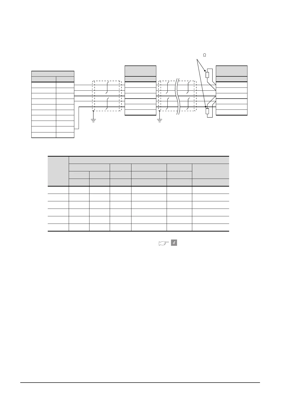
21.2.2 RS-485 cable
(5) RS-485 cable 5)
*1 Pin No. of temperature controller differs depending on model or optional function model. Refer to the following
table. The numbers in ( ) of the following table correspond to optional function models.
*2 Terminating resistor should be provided for a temperature controller which will be a terminal.
*3 Set the terminating resistor of GOT side to “Enable”.( Connecting terminating resistors)
*4 Connect FG grounding to the single-sided end of a cable shield line.
Signal
name
Model of temperature controller
SDC20 SDC21 SDC30 SDC31
SDC40A/40B/40G
(02, 04) (09) (03, 08) (040, 041, 045) (446, 546)
Pin No. Pin No. Pin No. Pin No. Pin No. Pin No.
RDA 17 18 27 18 27 59
RDB 18 19 28 19 28 60
SDA 15 16 25 16 25 57
SDB 16 17 26 17 26 58
SG 5 5 29 20 29 61
FG 4 4 4 3, 4 3, 4 3
*4
SG
FG
SDA1
RDA1
SDB1
RDB1
SDB2
SDA2
RDA2
RDB2
1
3
2
4
6
5
7
8
9
10
GOT side
*3
Signal name*1
Pin No.
Terminating resistor (120 1/2W)
RDA
SDA
SDB
SG
FG
RDB
Temperature
controller side
Signal name
*1
RDA
SDA
SDB
SG
FG
RDB
Temperature
controller side
Signal name
*1
*4
*2

 Loading...


