2.2 Preparatory Procedures for Monitoring
2.2.7 Checking for normal monitoring
2 - 43
1
OVERVIEW
2
BUS CONNECTION
3
DIRECT CONNECTION
TO CPU
4
COMPUTER LINK
CONNECTION
5
MELSECNET/10
CONNECTION (PLC TO
PLC NETWORK)
6
CC-Link CONNECTION
(INTELLIGENT DEVICE
STATION)
7
CC-Link CONNECTION
(Via G4)
8
ETHERNET
CONNECTION
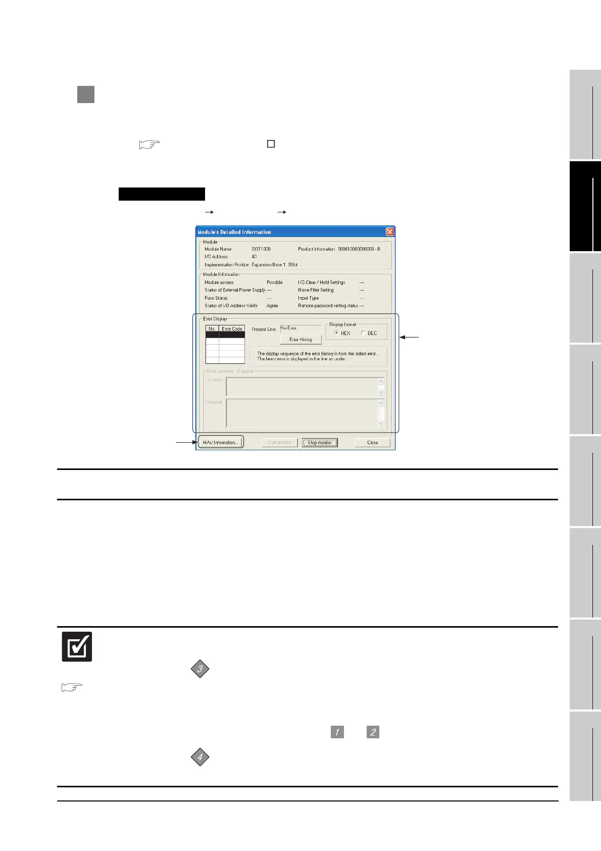
2 Check if the PLC CPU recognizes the GOT. (QCPU (Q mode) only)
Using the [System monitor] of GX Developer, check if the PLC CPU recognizes the GOT or not.
For details on GX Developer operations, refer to the following manual.
GX Developer Version Operating Manual
(1) Check the Module Name, I/O Address and Implementation Position. (The display example is based
on GX Developer Version 8.)
GX Developer [Diagnostics] [System monitor]
Startup procedure
All settings related to communications are complete now.
Create screens on GT Designer2 and download the project data again.
Section 2.4
Communication Check
Sheet
(1) When you have made sure that the Stage No. and Slot No. currently set to the
GOT are correct, mark the check sheet.
Communication setting (Stage No., Slot No.)
(2) If no problems are identified by and , then mark the check sheet.
Communication check (System alarm of GOT, [System monitor] on GX
Developer)
No error displayed
at all times
Not displayed
Check

 Loading...


