2.3 Precautions
2 - 45
1
OVERVIEW
2
BUS CONNECTION
3
DIRECT CONNECTION
TO CPU
4
COMPUTER LINK
CONNECTION
5
MELSECNET/10
CONNECTION (PLC TO
PLC NETWORK)
6
CC-Link CONNECTION
(INTELLIGENT DEVICE
STATION)
7
CC-Link CONNECTION
(Via G4)
8
ETHERNET
CONNECTION
3 Reset switch on GOT
When bus connection is used, the reset switch on the GOT does not function.
4 Powering OFF or resetting the PLC
(1) When turning OFF or resetting the PLC during monitoring
When turning OFF or resetting the PLC during monitoring, the system alarm (No.402: timeout
error) is generated.
When the PLC CPU is restored, the GOT automatically resumes monitoring.
Use System Information to reset the alarm.
For the System Information, refer to the following manual:
GT Designer2 Version
Screen Design Manual
(2) When turning OFF or resetting the PLC CPU before display of the user creation screen
When the PLC CPU is turned OFF or reset before the user creation screen is displayed on the
GOT, subsequent communications may be no longer possible.
In such a case, reapply the power to the PLC CPU and GOT.
(3) Precautions for connection of 3 GOTs or more (when connecting QCPU (Q mode))
(1) Restrictions in overall cable length to No. of GOTs
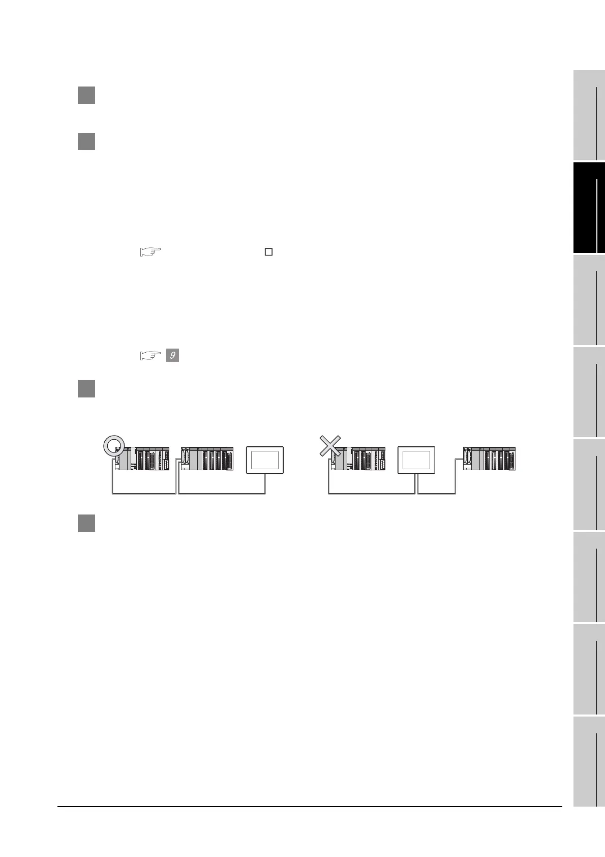
5 Position of the GOT
Always connect the GOT to the last base unit.
Connecting a GOT between base units is not allowed.
6 When the GOT is bus-connected to a PLC CPU without the communication driver
installed
When the GOT is bus-connected to a PLC CPU without the standard monitor OS and the
communication driver for the bus connection being installed onto the GOT, the PLC CPU is reset.
(Communications with the PLC CPU using GX Developer are no longer possible.)
In this case, disconnecting the bus connection cable from the GOT will cancel the reset status of the
PLC CPU.
 Loading...


