2.3 Precautions
2 - 47
1
OVERVIEW
2
BUS CONNECTION
3
DIRECT CONNECTION
TO CPU
4
COMPUTER LINK
CONNECTION
5
MELSECNET/10
CONNECTION (PLC TO
PLC NETWORK)
6
CC-Link CONNECTION
(INTELLIGENT DEVICE
STATION)
7
CC-Link CONNECTION
(Via G4)
8
ETHERNET
CONNECTION
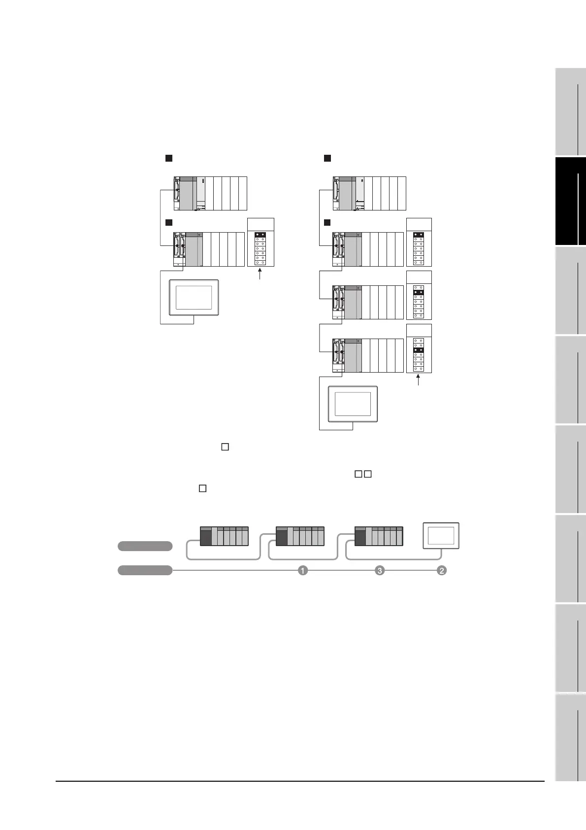
(3) When using a Q00J/Q00/Q01CPU
When a GOT is bus-connected to a Q00JCPU, number of extension stages including the GOT
must be 2 or less.
When a GOT is bus-connected to a Q00CPU or Q01CPU, number of extension stages including
the GOT must be 4 or less.
(4) When using the QA1S6 B extension base unit
A GOT is physically connected to the last of all extension base units. In the Stage No. setting,
however, assign the GOT as a stage next to the last Q B type extension base unit.
Assign the QA1S6
B type extension base unit as a stage next to the GOT.
Stage No. setting
connector
Stage No. setting
connector
Q00JCPU Q00CPU, Q01CPU
Main base unit
Extension base unit
Main base unit
Extension base unit
GOT
Stage No. :2
Extension
stage 1
Extension
stage 1
Extension
stage 2
Extension
stage 3
GOT
Stage No. :4
Stage No.
Q38B
Main base unit
Q68B
Extension base unit
QA1S68B
Extension base unit
Connection method
 Loading...


