6 System Commissioning and Functions NICE3000
new
User Manual
- 134 -
Function Code Parameter Name Setting Range Description
F8-05 Current car load 0–1023 It displays the current load condition in the car.
F8-06 Car no-load load 0–1023 It records the obtained no-load condition.
F8-07 Car full-load load 0–1023 It records the obtained full-load condition.
F8-06 and F8-07 respectively record the obtained no-load and full-load data after the load cell auto-
tuning is successful. You can also monitor the current load condition in the car by viewing F8-05.
When the value of F8-05 exceeds the value of F8-07, the system reports overload warning, forbids
door close, and stops elevator running.
Note that F8-05 to F8-07 record the binary data indicating the car load condition rather than the ratio
of actual car data to the rated car load.
2. Commissioning of digital full-load/overload switches
■ Wiring and parameter setting of digital full-load/overload switches
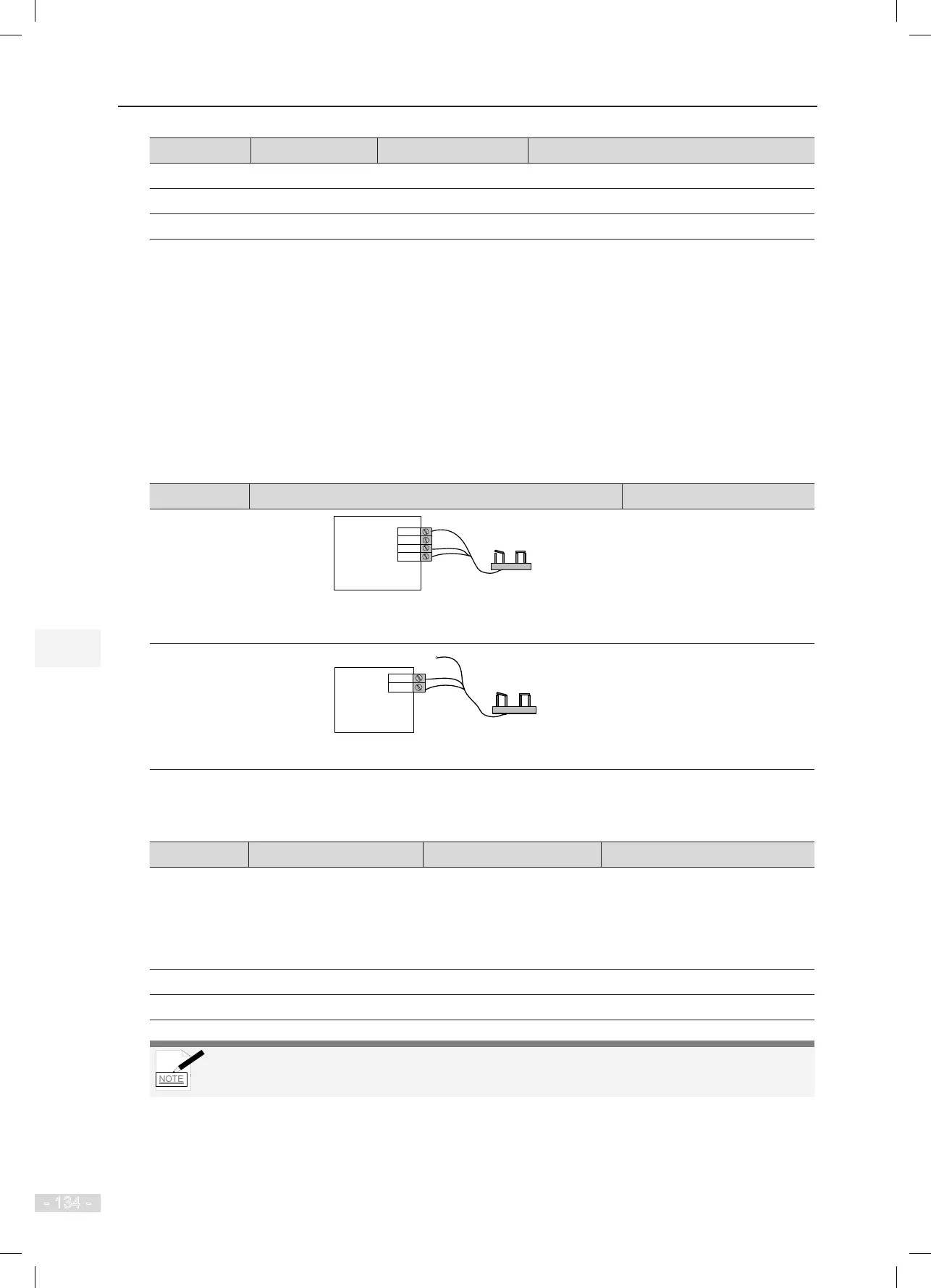
Type Wiring Diagram Parameter Setting
Connected to
CTB
CN3
X8
X7
P24
Digital load cell
MCTC-CTB-A
Full load
Overload
24 VDC
The full-load signal and overload signal must be respectively
connected to X7 and X8.
F5-36 = 1 (CTB digital input)
Connected to
MCB
CN9
X23
X24
Digital load cell
MCTC-MCB
24V
Full load
Overload
This gure takes X23 and X24 inputs only as an example.
F5-36 = 0 (MCB digital input)
The parameters involved in commissioning of digital full-load/overload switches are described in the
following table.
Function Code Parameter Name Setting Range Value
F5-36 Load cell input selection
0: MCB digital input
1: CTB digital input
2: CTB analog input
3: MCB analog input
0
F5-23 X23 function selection 0–199 47 (Full-load signal, NC)
F5-24 X24 function selection 0–199 46 (Overload signal, NC)
To guarantee running safety, the NC full-load/overload switches are recommended.
■ Monitoring of Full-Load/Overload Signal State
You can view F5-35 on the operation panel to see whether the full-load signal or the overload signal
is active.