4 Peripheral Devices and Options NICE3000
new
User Manual
- 78 -
Terminal Name
Function Terminal Wiring
DOWN
Interface for the down call button and indicator
Pins 2 and 3 are for down call input. Pins 1 and 4 are power supply for
the down call indicator (24 VDC output, load capacity: 40 mA).
1 2 3 4
Down call indicator
Down call
button
XF/ST
Interface for the re emergency and elevator lock switches
Pins 1 and 2 are for elevator lock input. Pins 3 and 4 are for re
emergency input.
1 2 3 4
Fire
emergency
input
Elevator
lock
input
J1
Terminal for setting the oor address.
Short J1, and press the UP button or DOWN button to set the oor
address (range 0–56). After the jumper cap is removed, the address is
automatically stored.
CN1
Modbus communication and power supply terminal
Pins 2 and 3 are for Modbus communication. Pins 1 and 4 are for DC
power supply.
◆
◆
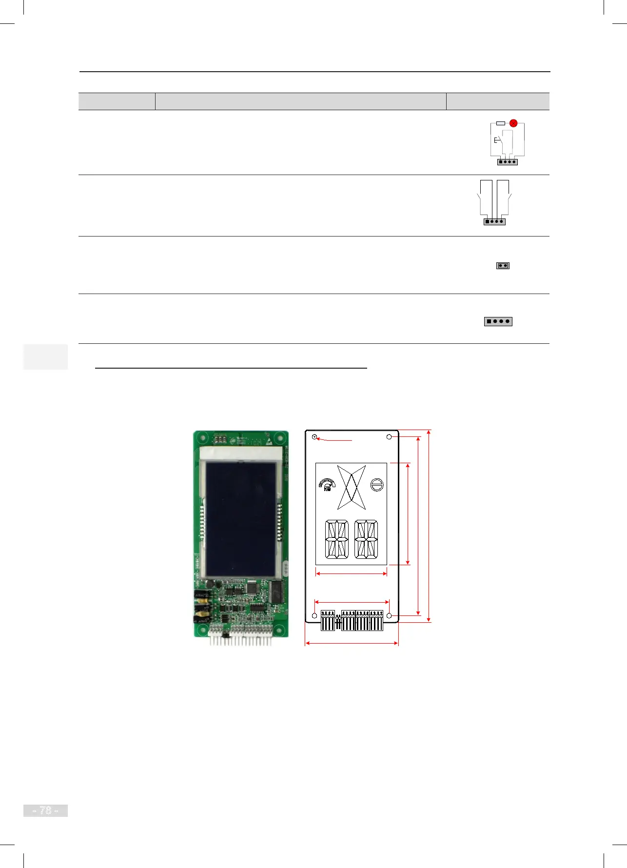
HCB-D2 (Ultrathin Segment LCD Display Board)
The following gure shows the appearance and dimensions of HCB-D2.
Figure 4-10 Appearance and dimensions of HCB-D2
4-φ3.5
56.0
134.0
70.0
144.
0
76.
0
49
CN1
J1
UP DOWN ST XF
Unit: mm
MCTC-HCB-D2