RF Planning and Deployment
84
ProSAFE Wireless Controller
Note: The Coverage icon is masked if you did not generate a heat map.
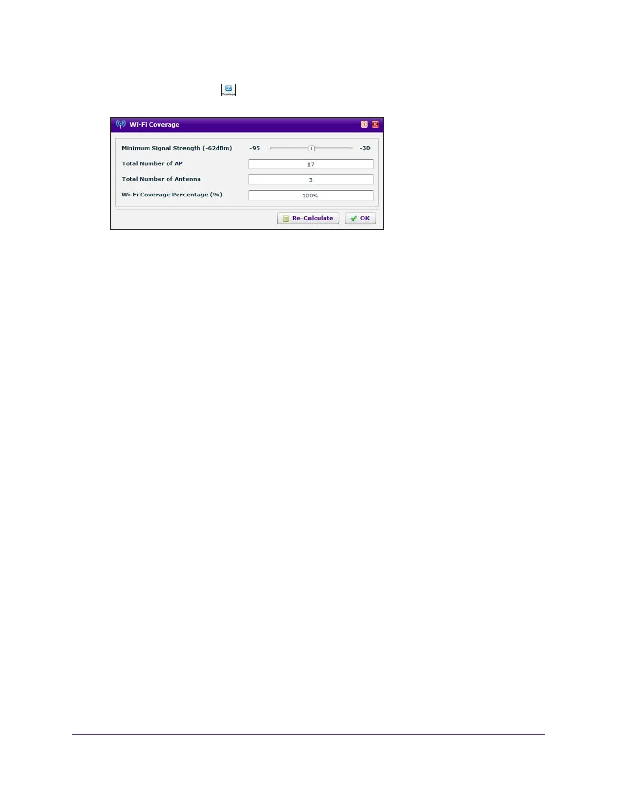
The Total Number of AP and Total Number of Antenna fields are based on the RF plan
and fixed. The Wi-Fi Coverage Percentage (%) field displays the WiFi coverage based
on the position of the Minimum Signal Strength slider at –62dBm.
10. Move the position of the Minimum Signal Strength slider to another dBm value.
11. Click the Re-Calculate button.
The Wi-Fi Coverage Percentage (%) field displays the WiFi coverage based on the new
dBm value.
12. Click the OK button.
The pop-up window closes.
If you want to change the actual minimum signal strength for an RF plan, run the WiFi
auto planning advisor again (see Use the WiFi Auto Planning Advisor to Generate an RF
Plan for a Floor on page 70).
Display or Change the WiFi Inventory for an RF Plan
The inventory for an RF plan of a floor displays all access points and antennas that you
added by running the WiFi auto planning advisor, the access points and antennas that you
added manually, or a combination of both.
To display or change the access point and antenna inventory for an RF plan:
1. Open a web browser, and in the browser’s address field, type the wireless controller’s IP
address.
By default, the IP address is 192.168.0.250.
The wireless controller’s login window opens.
2. Enter your user name and password.
3. Click the Login button.
The wireless controller’s web management interface opens and displays the Summary
page.
4. Select Plans > Planning.