4.10 Response Calibration
BP4610
4-76
4.10.4 Adjustment example
Generally, the capacitive load in the CV mode and the inductive load in the CC mode each form a
resonance circuit combined with the output impedance, resulting in a status in which oscillations are
easily generated.
Adjustment examples for the CV mode/capacitive load and CC mode/inductive load are presented
below.
(1) CV mode/capacitive load
Basically, both T and V are adjusted with their respective adjustment knobs.
While turning the I adjustment knob toward the right lowers the ringing frequency, making it
easier to suppress ringing with the V adjustment knob, normally the BP4610 is used with the I
adjustment knob turned all the way toward the left.
The operations when each adjustment knob is turned are described below.
• If T adjustment knob is turned to the right
The rise/fall become faster, but the ringing frequency also rises, and its amplitude increases.
• If V adjustment knob is turned to the right
The ringing amplitude is decreased, but the rise/fall become slower.
To make the rise/fall as fast as possible and suppressing ringing, perform adjustments by repeating
the following operation.
<1> Speed up the rise/fall with the T adjustment knob.
<2> Suppress ringing when it occurs with the V adjustment knob.
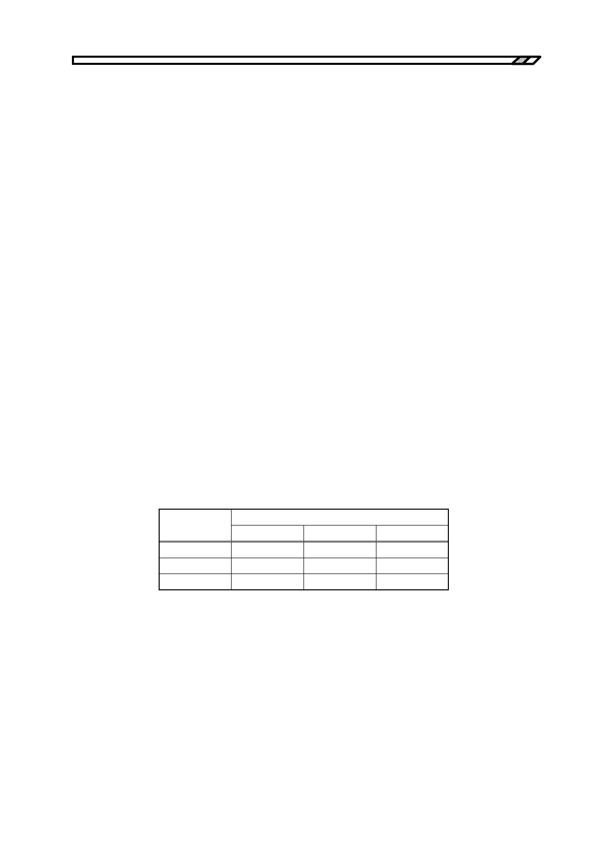
Table 4-24 shows adjustment examples for the three adjustment knobs, and Figures 4-23 to 4-25 show
output voltage waveform examples for each case.
Table 4-24. Adjustment Example for CV Mode/Capacitive Load
Calibration Position
C
T V I
10
µ
F 1 2.5 1
50
µ
F 1 4 1
100
µ
F 1 5 1