4.5 Sequence Operation
BP4610
4-43
4.5.6 Sequence operation setting example
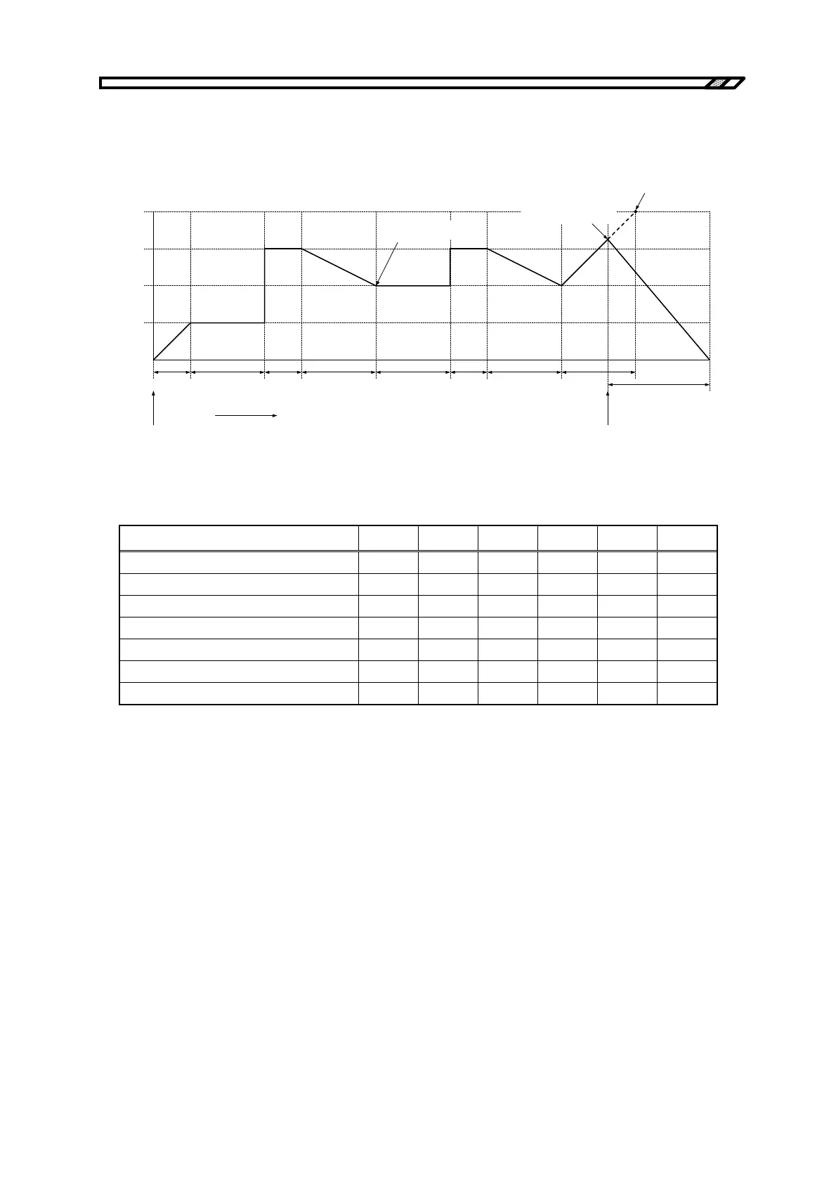
The procedure for newly setting a sequence operation, taking as an example the sequence shown in
Figure 4-20, is described below.
Step 1
(0.1 s)
2.50 V
5.00 V
0.00 V
7.50 V
10.00 V
Output voltage
Trigger input
Sequence start
Setting value of Step 5
SWEEP
SWEEP SWEEP
SWEEP
SWEEP
CONST
CONST
<1> <2>
<3>
STOP
KEEP
KEEP
Step 2
(0.2 s)
Step 3
(0.1 s)
Step 4
(0.2 s)
Elapsed time
Step 2
(0.2 s)
Step 3
(0.1 s)
Step 4
(0.2 s)
Step 5
(0.2 s)
Step 6
(0.3 s)
Jump to Step 6 upon
external trigger input
Jump to Step 2
"KEEP" setting is enabled
Figure 4-20. Sequence Transition Example (in CV-INT Mode)
Table 4-19. PROGRAM Setting List
Step No. 1 2 3 4 5 6
Step time (TIME) 0.1 0.2 0.1 0.2 0.2 0.3
DC voltage (DC VOLT) 2.50 2.50 7.50 5.00 10.00 0.00
DC voltage operation type SWEEP KEEP CONST SWEEP SWEEP SWEEP
Step termination (STEP TERM) CONT CONT CONT CONT CONT STOP
Jump step (JUMP STEP) 0 0 0 2 0 0
Jump count (JUMP NUM) 1 1 1 1 1 1
Branch 0 (BRANCH0) 0 0 0 0 6 0
Since the jump step in Step 4 is set to 2, at the end of Step 4, the operation jumps to Step 2 (<1> in
Figure 4-20). At this time, the settings of Step 2, DC voltage value (2.50 V) and DC voltage operation
type (KEEP as 5.00 V), are incompatible, but since the operation type setting always takes precedence,
DC voltage value = 5.00 V is used.
Since Jump count = 1 is set, the operation jumps to Step 5 upon completion of Step 4 after the jump
(<2> in Figure 4-20).
Step 5 is set to Step time = 0.2 s and DC voltage value = 10.00 V, but if a trigger input occurs midway,
the operation jumps to Step 6 at this point (<3> in Figure 4-20).