4.10 Response Calibration
BP4610
4-78
(2) CC mode/inductive load
Basically, adjustments can be performed with the T and I adjustment knobs.
Turning the V adjustment knob to the right lowers the ringing frequency and makes it easier to
suppress ringing with the I adjustment knob, but normally the BP4610 is used with the V
adjustment knob turned all the way to the left.
The operations when the adjustment knobs are turned are described below.
• If T adjustment knob is turned to the right
The rise/fall become faster, but the ringing frequency also rises, and its amplitude increases.
• If I adjustment knob is turned to the right
The ringing amplitude is decreased but the rise/fall become slower.
To make the rise/fall as fast as possible and suppress ringing, perform adjustments by repeating
the following operations.
<1> Speed up the rise/fall with the T adjustment knob.
<2> Suppress ringing when it occurs with the I adjustment knob.
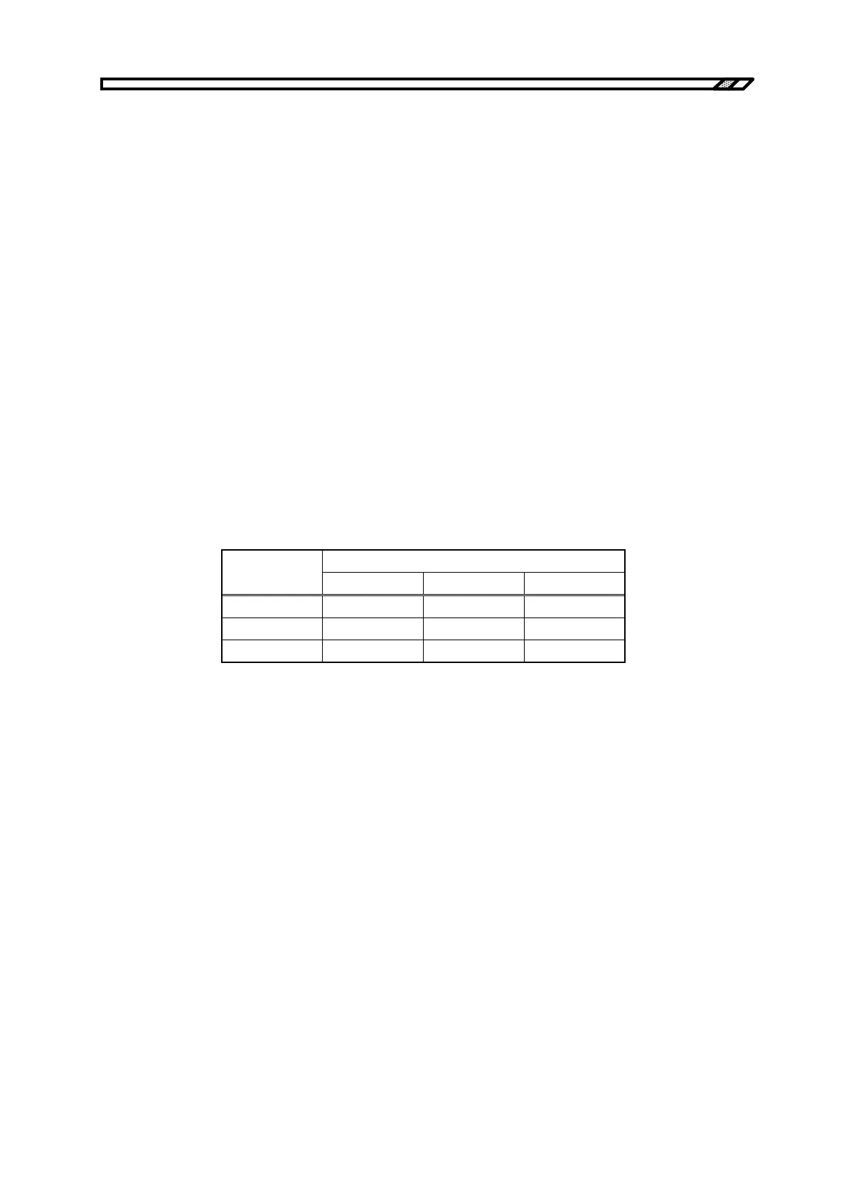
Table 4-25 shows adjustment examples for the three adjustment knobs, and Figures 4-26 to 4-28 show
output current waveform examples for each case.
Table 4-25. Adjustment Example for CC Mode/Inductive Load
Calibration Position
L
T V I
150
µ
H 5 1 7
390
µ
H 3 1 7
1.6 mH 1 1 7