2.4 Connection to I/O terminals
BP4610
2-6
!
2.4.2 Connection to output pins
The outputs are insulated between the power supply inputs. The “Lo” output terminal is connected to
the chassis.
For the connection to the output terminals, use a cable of 2 mm
2
or more and a round crimp terminal
with a sleeve.
For the wiring to the load, use a wire that is as thick as possible, twisting the wire together so that it
does not form a loop, and not making it any longer than necessary.
!
OUTPUT
Hi Lo
LINE
USB
CONTROL
質量 MASS
26kg
!
警告
!
WARNING
!
警告
!
WARNING
!
警告
!
WARNING
Output
terminals
Figure 2-4. Output Terminals
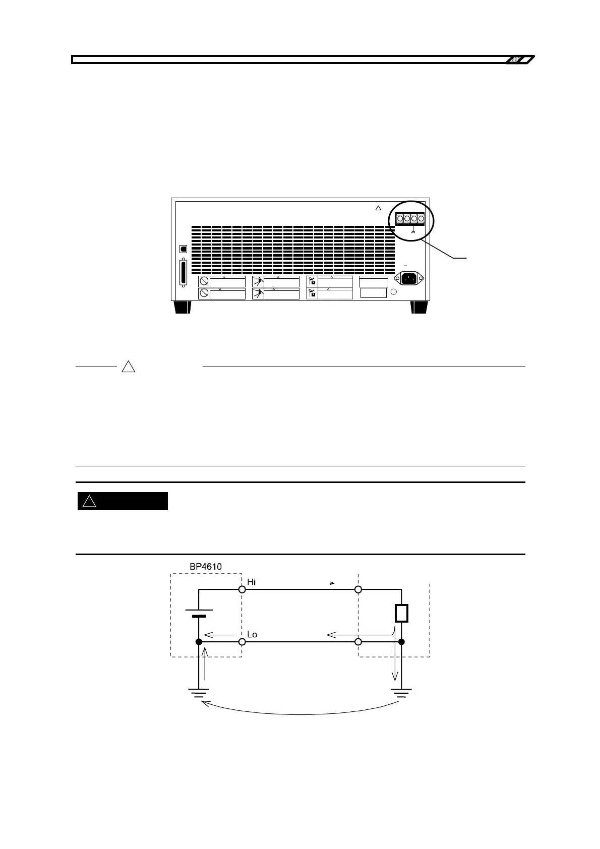
Note that since the “Lo” output terminal of the BP4610 is grounded, it is not possible to connect multiple
outputs of the BP4610 in series.
Also, do not connect a grounded load or measuring instrument whose input block is grounded to the
output terminal of the BP4610, as this may cause some of the output current to leak to the protective
grounding wire of the power supply and have an unpredictable effect on the load or measuring
instrument.
During output, absolutely never touch the output terminals.
For safety’s sake, be sure to use the BP4610 with the supplied pin covers mounted.
Figure 2-5. Connection to Grounded Load or Measuring Instrument
WARNING
!
CAUTION
Output current
Load, measuring
instrumen