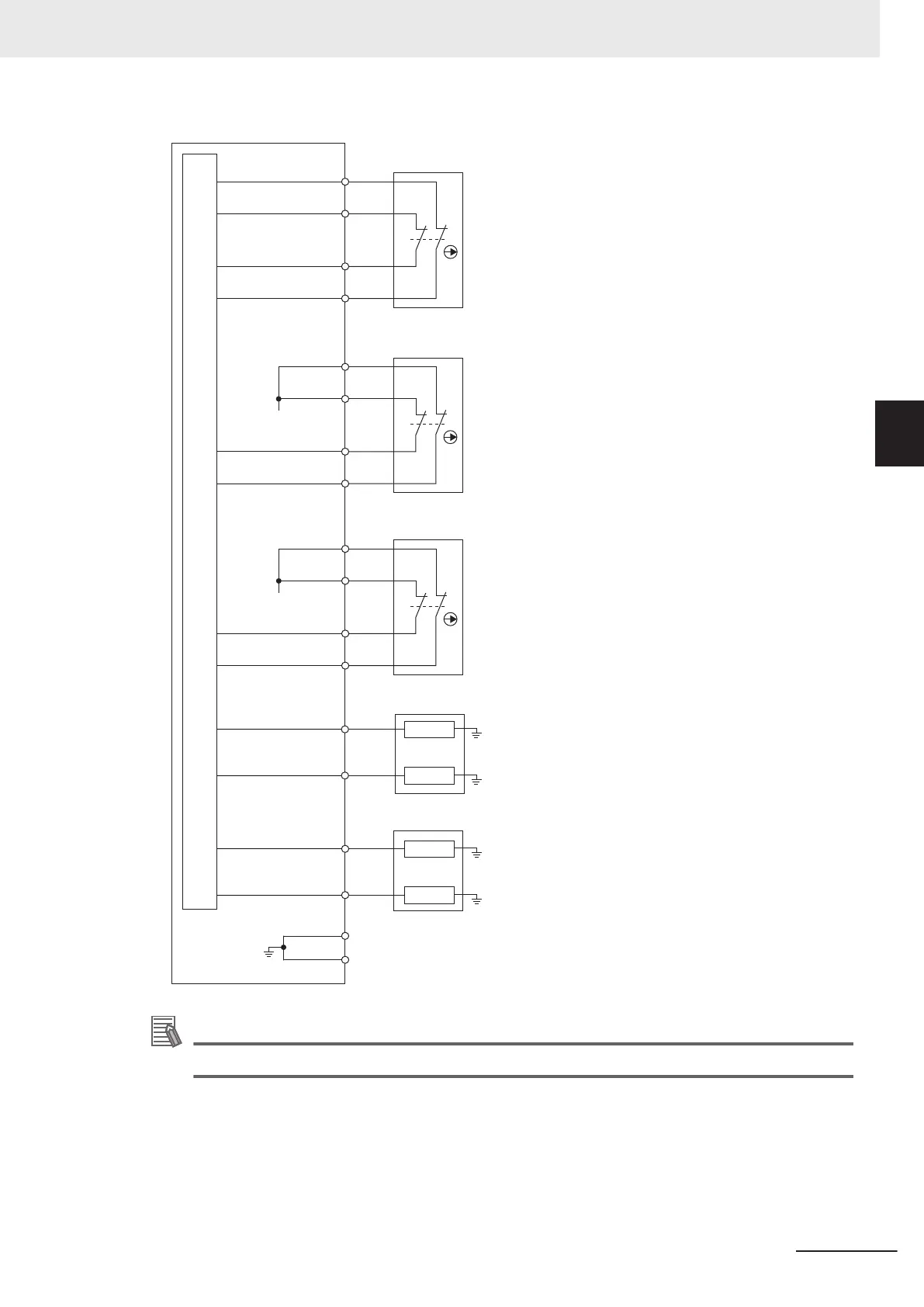
User-supplied
Emergency Stop
Devices
PIN 10
PIN 11
PIN 2
PIN 1
+ 24 VDC
PIN 6
PIN 7
PIN 4
PIN 13
Load
Load
SCPU Connector
Internal circuits
PIN 3
PIN 12
PIN 5
PIN 14
User-supplied
Protective Stop
Devices
Load
Load
PIN 9
PIN 18
Alternate
Safety Zone
No Motion
Safety
Outputs
+ 24 VDC
PIN 15
PIN 16
PIN 8
PIN 17
Additional Information
Refer to 2-4-16 Safety Function Performance Levels on page 2-20 for more information.
AUX PLC
The AUX PLC connector in the User Connections area provides 24 VDC for user-supplied NX units
that may be added to the system.
Use the information below to understand AUX PLC connections.
The following figure shows the pin arrangements for the AUX PLC connector on the AMR.
3 Installation
3-23
AMR (Autonomous Mobile Robot) MD-series Platform User's Manual (I681)
3-5 Electrical Connections
3
3-5-1 User Connections Area

 Loading...


