LIGHTS
The LIGHTS connector in the User Connections area provides outputs for user-supplied signaling
devices such as signal beacons or buzzers.
Use the information below to understand all LIGHTS connections.
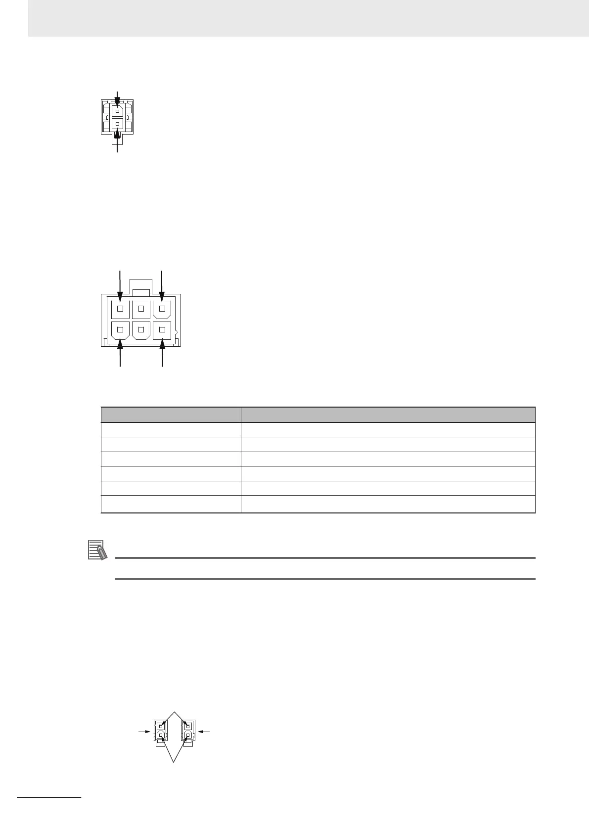
The following figure shows the pin arrangements for the LIGHTS connector on the AMR.
The information in the table below describes the signal designations for the I/O 1 connector.
Pin Number Description
1 Red light
2 Ground
3 Yellow light
4 Green light
5 Ground
6
Buzzer
*1
*1. The buzzer signal will turn ON when the AMR warning buzzer turns ON.
Additional Information
Refer to 4-21 Light Discs and Optional Beacon States on page 4-41 for more information.
BUZZ
The User Connections area contains a connector used for adding extra buzzers.
Refer to the following sections for more information about the behavior of the BUZZ signals.
• 4-24 Warning Buzzer on page 4-50
• 1-6-4 Additional Warning Buzzers on page 1-28.
Use the information below to understand all buzzer connections.
The following figure shows the pin arrangements for the BUZZ connectors on the AMR.
Buzzer 1
Buzzer 2
24 VDC
Ground
3 Installation
3-24
AMR (Autonomous Mobile Robot) MD-series Platform User's Manual (I681)

 Loading...


