3-73
If
this signal is ON, the Inverter will decelerate the motor to stop according to deceleration time 2 set with
n022 when the Inverter detects a voltage drop of power supply to the Inverter.
D Up/Down Command (Set Value = 25)
The up/down command controls the output frequency according to input to S5 and S6.
S5
(multi-function input 4) will be used for the up command, S6 (multi-function input 5) will be used for
the down command, and value set with n038 will be ignored if n039 is set to 25.
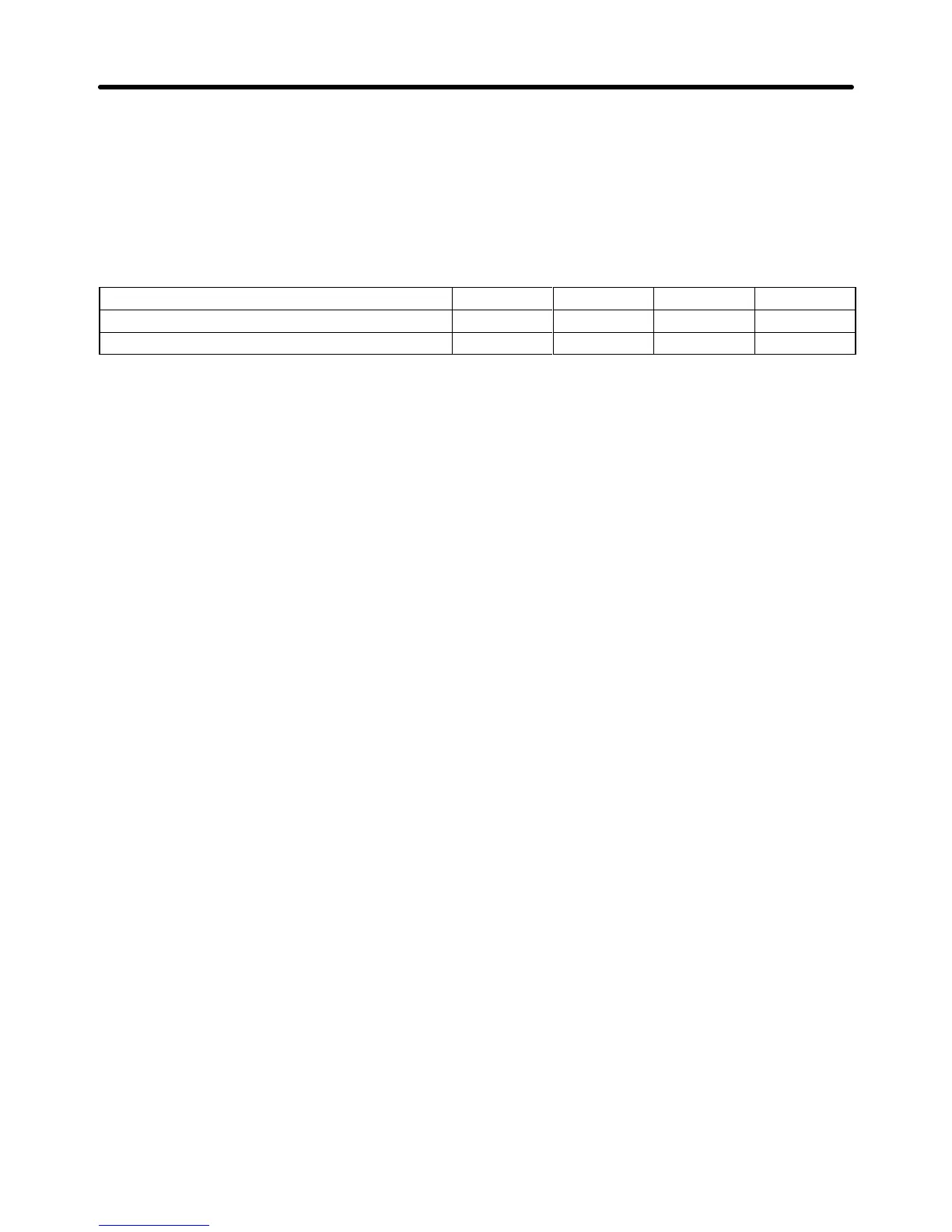
Multi-function input 4 (S5): Up command ON OFF ON OFF
Multi-function input 5 (S6): Down command OFF ON ON OFF
Operation status Acceleration Acceleration Hold Hold
Note 1. The up/down command is valid
only if n002 (i.e., operation mode selection) is set to 1 or 3.
Note 2. The
Inverter will accelerate or decelerate the motor according to the acceleration time or
de
-
celeration time set with n019 to n022 if the up/down command is input.
Note 3. The
following are the upper and lower limits of the output frequency when the Inverter acceler
-
ates or decelerates the motor with the up/down command.
Upper limit: Maximum frequency (n012) x output frequency upper limit (n030)/100
Lower limit: Maximum frequency (n012) x output frequency lower limit (n031)/100
If an analog frequency reference is input through the FV or FI terminal and the value of the
analog frequency reference is larger the above lower limit, the lower limit of the output fre-
quency will be determined by the analog frequency reference.
Note 4. The
initial
output frequency is 0.0 Hz if n039 is set to 25. The output frequency will reach the
lower limit when the up/down command is input.
Note 5. Turn
ON input to S5 or S6 while the run command is OFF to set the frequency reference used
by the Inverter to zero.
Note 6. The multi-step speed command is invalid if n039 is set to 25.
Preparing for Operation Chapter 3
 Loading...


