3-80
n049 Multi-function Analog Output Gain
Setting range 0.01 to 2.00 Unit Times Default setting 1.00
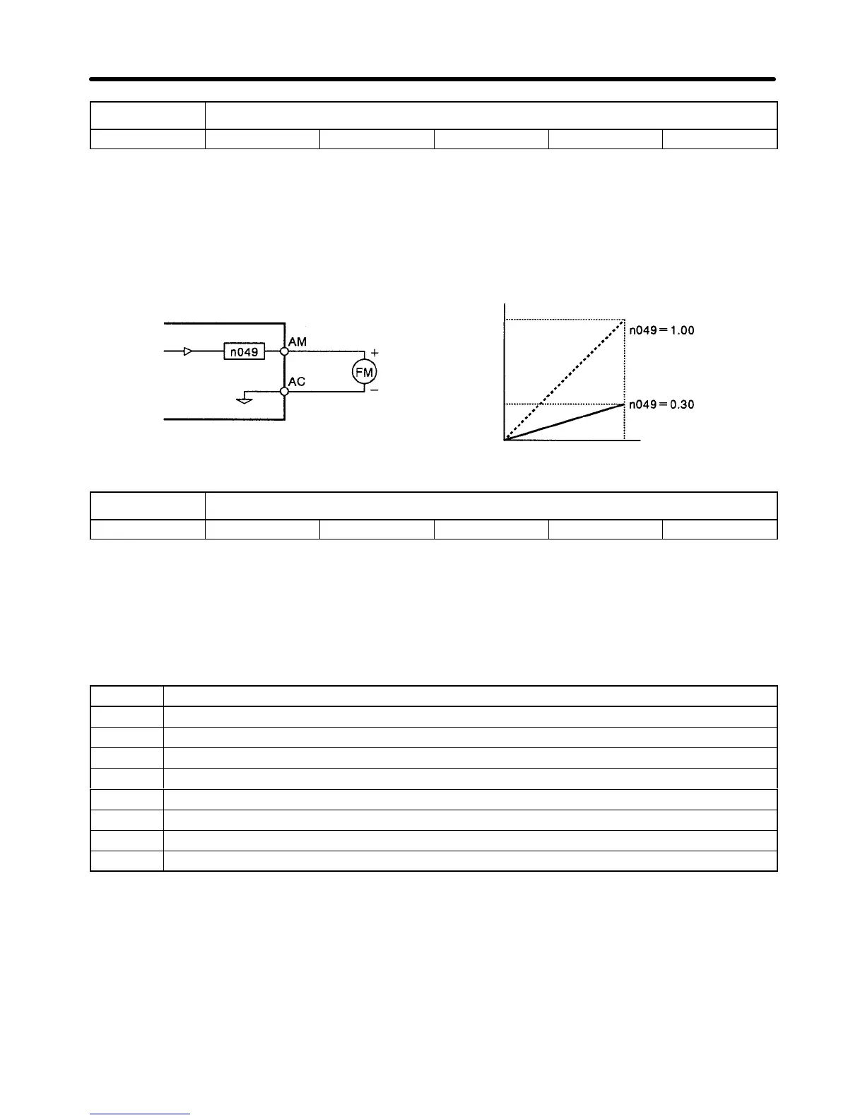
• The parameter n049 is used to adjust the analog output gain.
Set Values
• Set n049 to the result obtained from dividing the voltage of the full analog output by 10 V.
• For
example, set n048 to 0 and n049 to 0.30 when
connecting multi-function analog output terminals
AM and AC to a frequency meter that operates at 3 V maximum. Refer to the following diagram.
Frequency meter
(FS: 1 mA at 3 V)
Analog Output
Default set
Maximum frequency
10 V
3 V
n050 Carrier Frequency
Setting range 1 to 9 Unit --- Default setting See note
Note The default-set value of n050 varies with the Inverter model.
• Set the switching frequency (carrier frequency) of the output transistor of the Inverter with n050.
• The
noise generation and current
leakage of the Inverter will be low if the carrier frequency is set low
, in
which case, the motor will generate a more metallic noise.
Set Values
Set value Description
1 2.5 kHz
2 5.0 kHz
3 8.0 kHz
4 10.0 kHz
5 12.5 kHz
6 15.0 kHz
7 to 9 Varies in proportion to output frequency up to 2.5 kHz. (Refer to the following graphs)
10 7.0 kHz
Note 1. The carrier frequency setting range varies depending on the Inverter capacity.
200-V class and 400-V class, 22 kW max.: 0.4 to 15.0 kHz max.
200-V class, 30 to 75 kW; 400-V class, 30 to 160 kW: 0.4 to 10.0 kHz max.
400-V class, 185 to 300 kW: 0.4 to 2.5 kHz max.
Note 2. For
a 400-V Inverter
, if the carrier frequency is set to a value higher than the default setting, the
Inverter’s rated output current will decrease as shown in the following table. If the Inverter
overload
“OL2” is detected prior to the motor overload “OL1,” decrease the carrier frequency
setting.
Preparing for Operation Chapter 3
 Loading...


