2-21
H Wiring on the Input Side of the Main Circuit
D Installing a Molded-case Circuit Breaker
Always
connect
the power input terminals (R/L1, S/L2, and T/L3) and power supply via a molded case
circuit breaker (MCCB) suitable to the Inverter.
• Install one wiring circuit breaker per Inverter.
• Choose an MCCB with a capacity of 1.5 to 2 times the Inverter’s rated current.
• For
the MCCB’
s time characteristics, be sure to consider the Inverter
’
s overload protection (one min
-
ute at 150% of the rated output current).
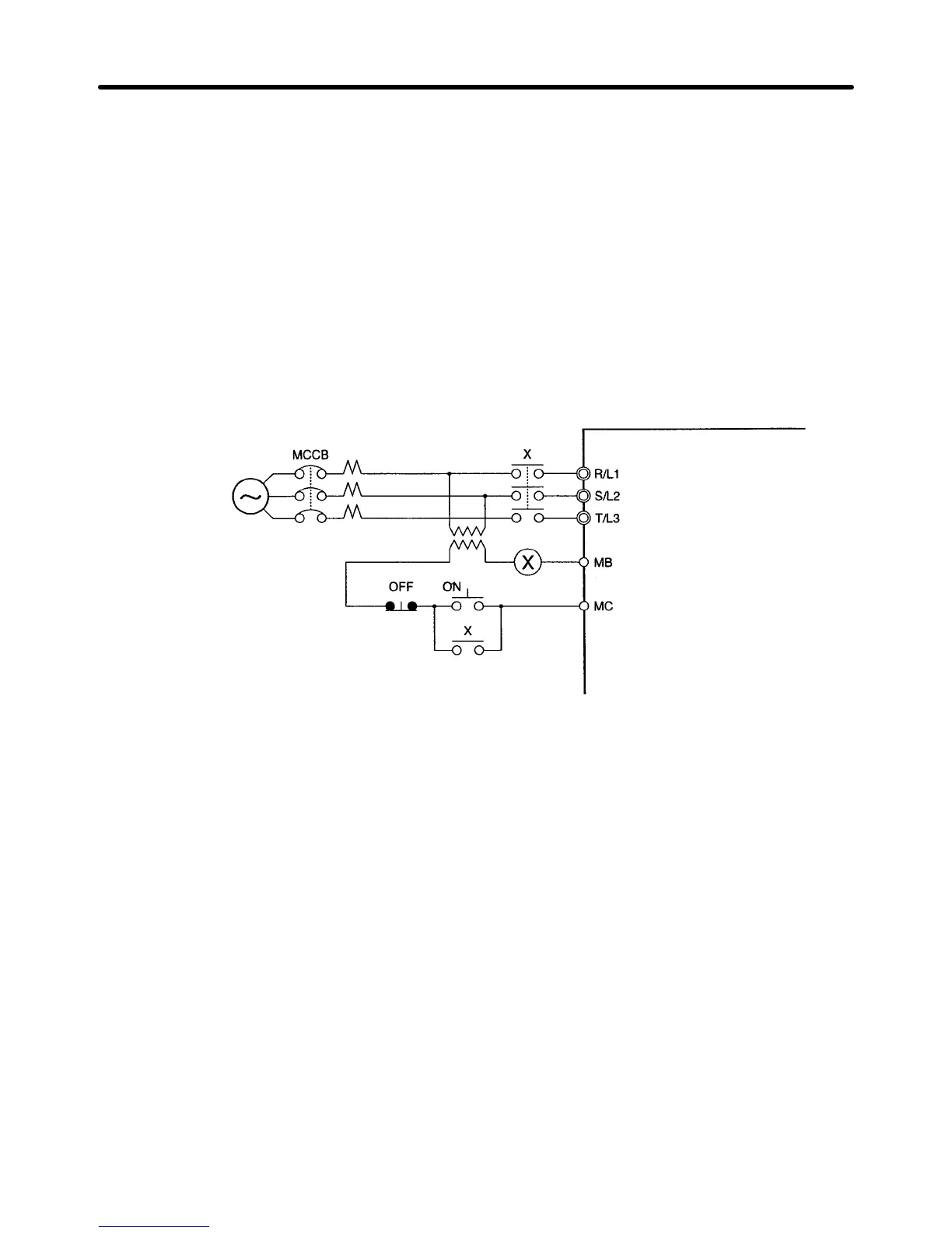
• If
the MCCB is
to be used in common among multiple Inverters, or other devices, set up a sequence
such that the power supply will be turned OFF by a fault output, as shown in the following diagram.
3-phase/
Single-phase
200 V AC
3-phase
400 V AC
Power
supply
Inverter
Fault output (NC)
(See note.)
Note Use a 400/200 V transformer for a 400-V model.
D Installing a Ground Fault Interrupter
Inverter outputs use high-speed switching, so high-frequency leakage current is generated.
In general, a leakage current of approximately 100 mA will occur for each Inverter (when the power
cable is 1 m) and approximately 5 mA for each additional meter of power cable.
Therefore,
at the power supply input area, use
a special-purpose breaker for Inverters, which detects
only the leakage current in the frequency range that is hazardous to humans and excludes high-fre-
quency leakage current.
• For the special-purpose breaker for Inverters, choose a ground fault interrupter with a sensitivity
amperage of at least 10 mA per Inverter.
• When
using a general leakage breaker
, choose a ground fault interrupter with a sensitivity amperage
of 200 mA or more per Inverter and with an operating time of 0.1 s or more.
Installation Chapter 2
 Loading...


